Page 100 FlexZone Product Guide
UCM configuration
To use UltraLink modular I/O system outputs to report FlexZone alarm and supervision conditions
establish a UCM connection to the FlexZone processor.
Select the Remote Cfig tab and specify the outputs that will activate to annunciate the required
alarm and supervision conditions (see Figure 94:
).
Select the Side A Cfig or Side B Cfig tabs to assign outputs to Cable segments for reporting Zone
alarms (Figure 95:
).
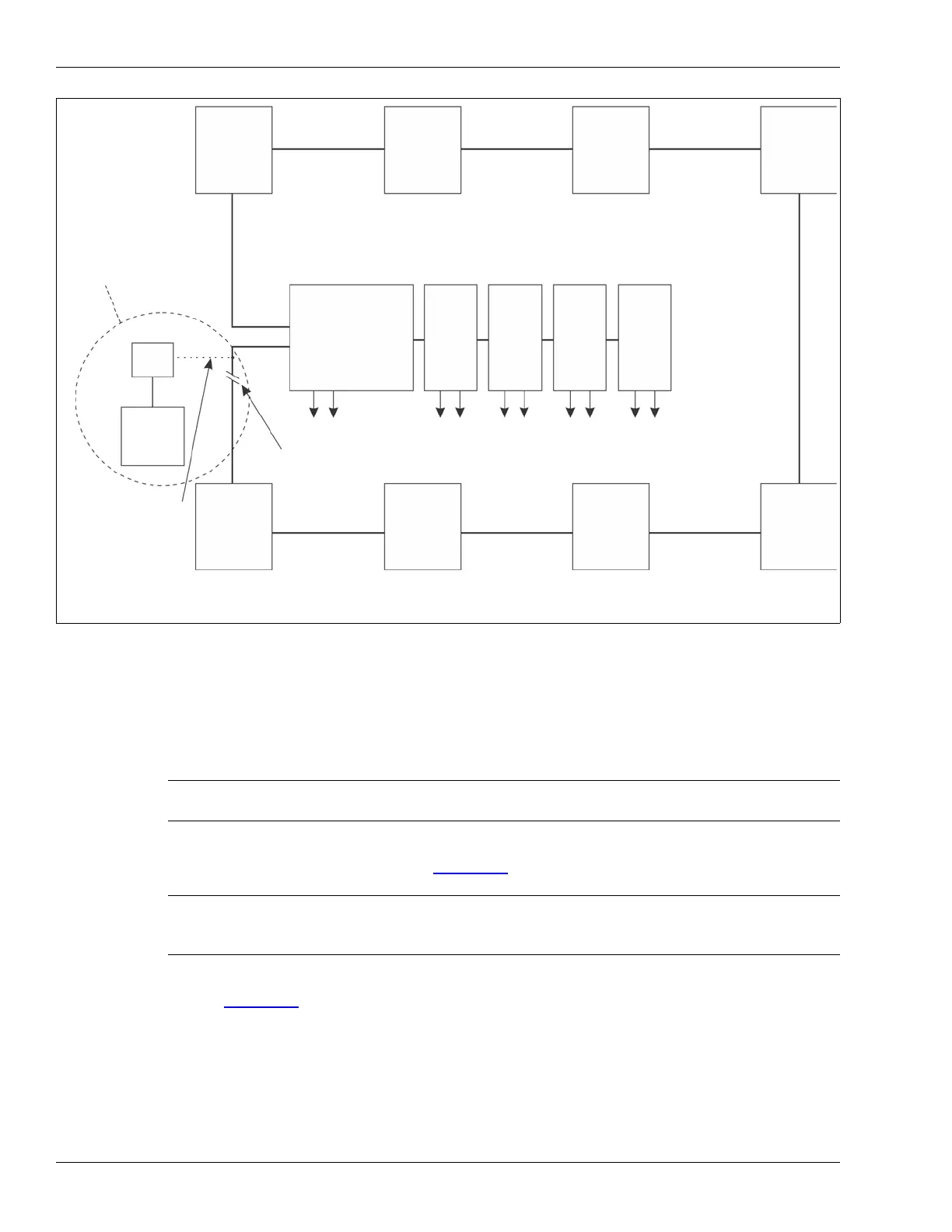
Figure 93: NM Mode block diagram
Note Refer to the UltraLink Modular I/O system instruction sheet and the
UCM help file for additional details on NM Mode operation.
Note Output assignments for Comm Fail and device mismatch for each
connected device are made via a UCM connection to the UltraLink
processor (see 00DA1003-001).
To setup and access a Silver Network for maintenance access the UltraLink I/O processor must be taken
UltraLink I/O processor
card 1
O/P
card 3
O/P
card 4
O/P
card 2
O/P
UltraLink I/O output modules
A-side
B-side
FlexPS
processor
FlexZone
processor
FlexZone
processor
FlexPS
processor
processor
OmniTrax
processor
OmniTrax
processor
XField
node 1
node 2
node 3
node 4
node 5
node 6node 7
node 8
Comm Fail
O/P
alarms alarms
alarms alarms
alarms
Mismatch
nodes 1 - 8
Silver Network
mini
NM
PC
temporary connection
temporary break in Silver Loop *
NIU
optional temporary
*
out of NM Mode, and a temporary connection is required between the NM PC (via a mini-NIU) and the
Silver Loop. A temporary break in the NM Mode Silver Loop network is also required.
to Silver Network for
maintenance access
Loop configuration
connection to Silver Network
Manager to provide remote
maintenance access to the
UltraLink I/O and the
connected sensors
FlexZone
processor