Installing the FlexZone processor
Page 56 FlexZone Product Guide
Processor wiring connections
You make FlexZone processor wiring connections on removable terminal blocks. The screw
terminals accept wire sizes from 12 to 24 AWG, with a 6 mm (¼ in.) strip length. Remove the
terminal blocks to make the wiring connections. Reinstall the blocks after the connections are
complete, and verified. Figure 38:
shows the sensor cable to processor connection procedure.
Figure 66:
shows the input/output wiring connections to the FlexZone processor. Figure 67: shows
the input/output wiring connections to the FlexZone option cards. Figure 68:
to Figure 73: show
the Silver Network wiring options.
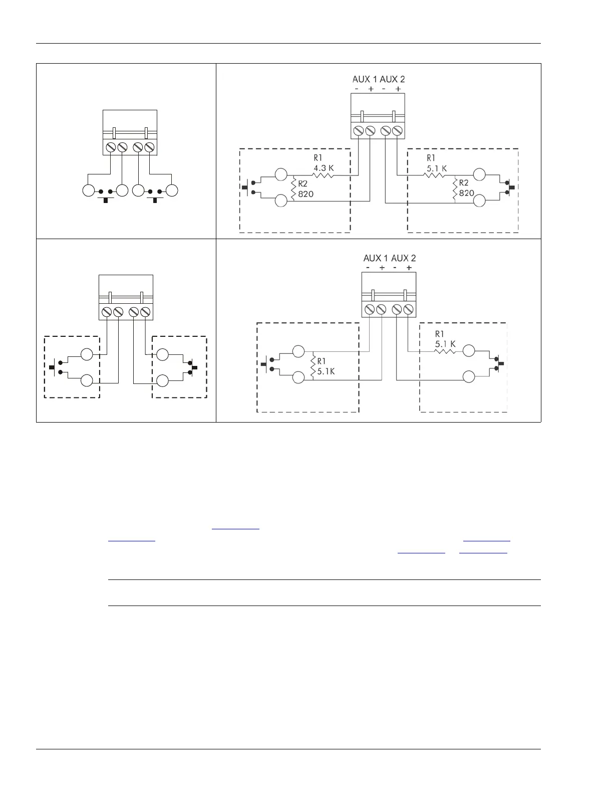
Figure 65: Self-test/Auxiliary device input wiring examples
Note See instruction sheet 00DA1503 for information about installing the
optional relay output card and dry contact input card.
NO self-test inputs
Local control mode
dual resistor supervision
NO alarm
dual resistor supervision
NC alarm
Remote control mode
cut and short supervision
cut and short supervision
NO auxiliary input
unsupervised
NC auxiliary input
unsupervised
Remote control mode
single resistor supervision
NO alarm
single resistor supervision
NC alarm
Remote control mode
cut supervision
short supervision