Initial processor setup
Page 72 FlexZone Product Guide
Power over sensor cables
If this processor receives power from a 48 VDC power supply and will distribute power over the
sensor cables to other processors, you must setup the power distribution scheme via the UCM. If
this processor receives power over the sensor cables, and will provide power to an auxiliary device
via the power connector (T4) you must setup the auxiliary power output function via the Aux Cfig
tab on the UCM.
The UCM Diagnostics Status field includes three indicators along with voltage and current
readings for Cable A, Cable B and Input/Aux (Auxiliary power output - Volt readings only). There
are also three test checkboxes that are used to test and verify the selected power distribution
function.
Use the test checkboxes on the Status screen to temporarily change the power distribution
function (Cable A power distribution, Cable B power distribution, Auxiliary power output via T4).
Changes made go into effect immediately and revert to the original configuration when the UCM is
disconnected.
1. On the UCM Status tab in the Diagnostic Status field, select the Cable A checkbox to verify the
power distribution function, if this processor will distribute power over the A side cable.
2. Select the Cable B checkbox to verify the power distribution function, if this processor will
distribute power over the B side cable.
Note The Cable Supervision Mode must be set to cable pair supervision
before the test function can be used.
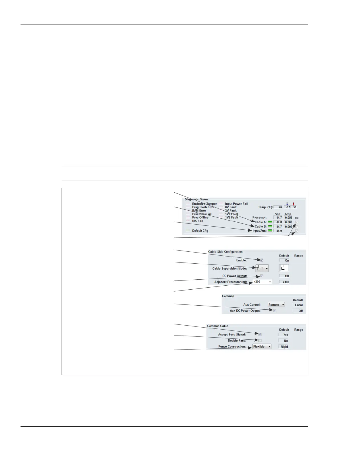
Figure 81: FlexZone power over sensor cable settings
select cable pair supervision to enable
green indicator indicates power distributed
green indicator indicates power distributed
over B side sensor cable
power distribution over the sensor cable
green indicator indicates auxiliary power output
over A side sensor cable
available via T4 (2 W)
select the test check-box to verify that
the specified function is operational
select the Enable checkbox to
select the DC Power Output checkbox to
distribute power via the selected cable side
select the Aux DC Power Output checkbox to
supply 2 W of power to an auxiliary device via T4
NOTE: The Aux Power Output voltage is equal to the voltage received over the sensor cables.
Power over the sensor cables and auxiliary DC power output are available only when
the processor’s input voltage is 38 VDC or greater.
turn ON the cable side
specify the cable length to the connected processor
uncheck the Accept Sync Signal checkbox only
if this processor will be the Sync Master
select the Double Pass checkbox if this processor
will monitor a double pass of sensor cable
specify the type of fence (Rigid or Flexible)