Installing the sensor cable
Page 50 FlexZone Product Guide
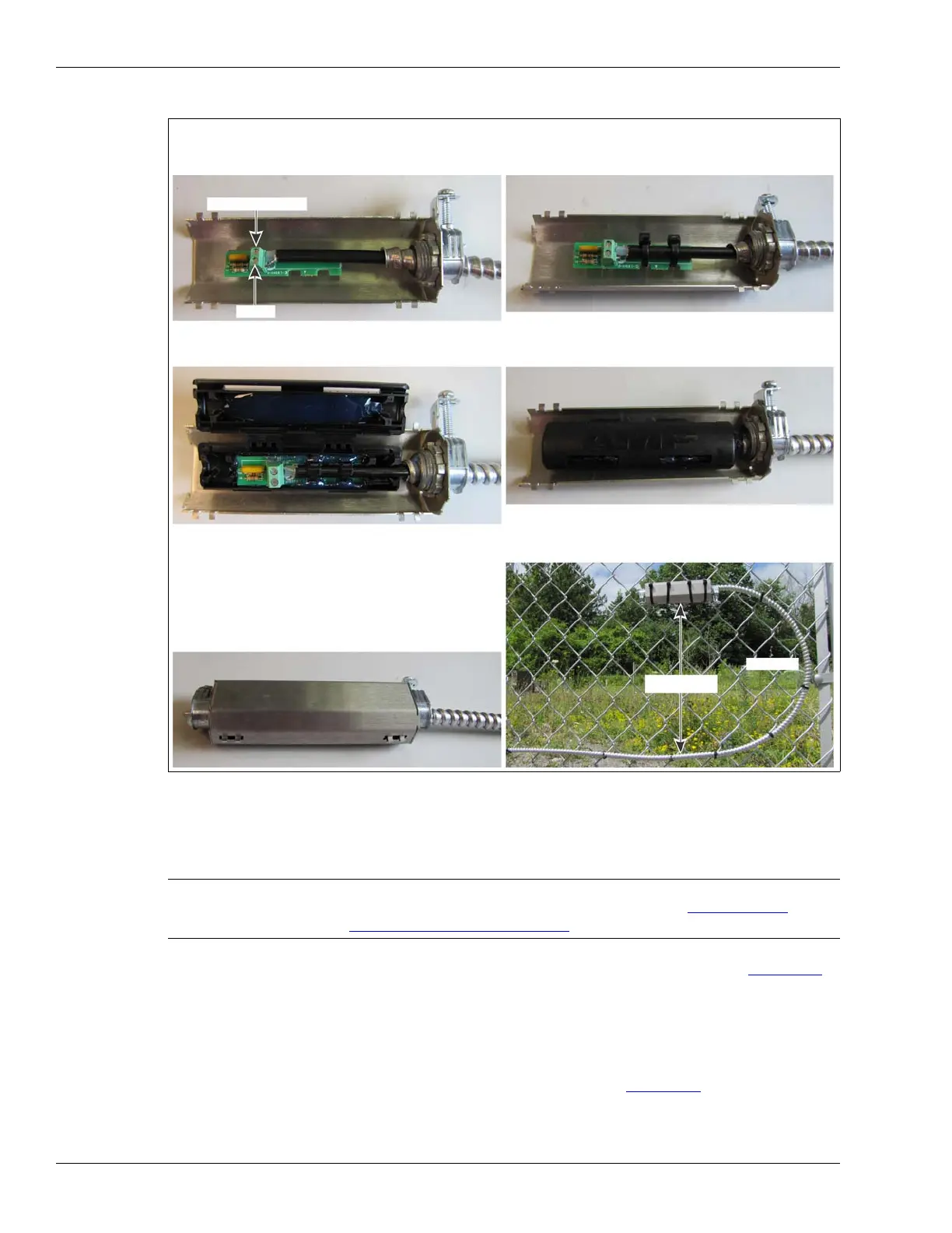
3. Make the termination.
Connecting armored sensor cable to the processor
1. Remove the two 3/8 in. sensor cable glands from the enclosure’s right side (see Figure 61: ).
2. Carefully drill the 2 holes to fit the 1/2 in. cable glands (22 mm; 7/8 in. bit size).
3. Ensure that all metal shavings from the drilling are removed from the enclosure.
4. Remove the split rubber grommets from inside the 1/2 in. cable glands.
5. Remove 3 in. of the armored jacket.
6. Prepare the sensor cable for connecting to the processor (see Figure 34:
).
7. Pass the sensor cable through the cable gland into the enclosure then through the nut.
8. Loosely install the 1/2 in. cable glands.
Figure 59: Making the termination
CAUTION Remove the processor circuit card from the enclosure BEFORE drilling
the cable ports to fit the 1/2 in. cable glands (see Removing the
processor assembly on page 90).
center conductor
shield
drip loop
a. Feed the cable through 1/2 of the armored shell, and
follow the screening to connect the center conductor
and shield to the terminal block on the CCA.
b. Secure the sensor cable to the CCA with two of the
cable ties. Keep the cable ties on the same side and
at a 45º angle to the flat plane of the CCA.
e. Center the terminator in the enclosure on the side
with double cable guide bars. Press the cable firmly
into the guide bars and the terminator into the gel.
f. Snap the enclosure shut so that the two locking tabs
are latched in the slots, and the enclosure is closed
g. Fit the two halves of the armored shell together with
and locked with gel oozing out of the end.
the enclosure centered inside. Ensure the clamps are
oriented upward, then tighten the clamps.
h. Raise the shell 30 cm (12 in.) above the cable run,
and attach it to the fence horizontally with 4 large
cable ties. For increased security, use stainless steel
30 cm (1 ft.)
straps or wire.