Installing the sensor cable
Page 44 FlexZone Product Guide
Gate disconnect assembly
The gate disconnect assembly protects gates that are infrequently used. The gate can be opened
and closed by manually separating the connection (see Figure 50:
). When the assembly is
opened, a supervision alarm is generated. When the assembly is closed the gate is protected.
Installation instructions
1. Place the male cap stay wire over the open end of the non-detecting cable on the male
connector. Put the cap in place on the connector during installation.
2. Wrap a gear clamp (customer supplied) around the fixed post on the opening side of the fence
on which the gate disconnect will be mounted.
3. Before tightening the clamp, position the L-bracket against the post under the clamp.
4. Tighten the clamp until the assembly is firmly attached to the post.
5. Dress the non-detecting cables to the splice kits with cable ties.
6. Follow the directions for a standard splice.
7. Attach the rubber cover over the disconnect assembly.
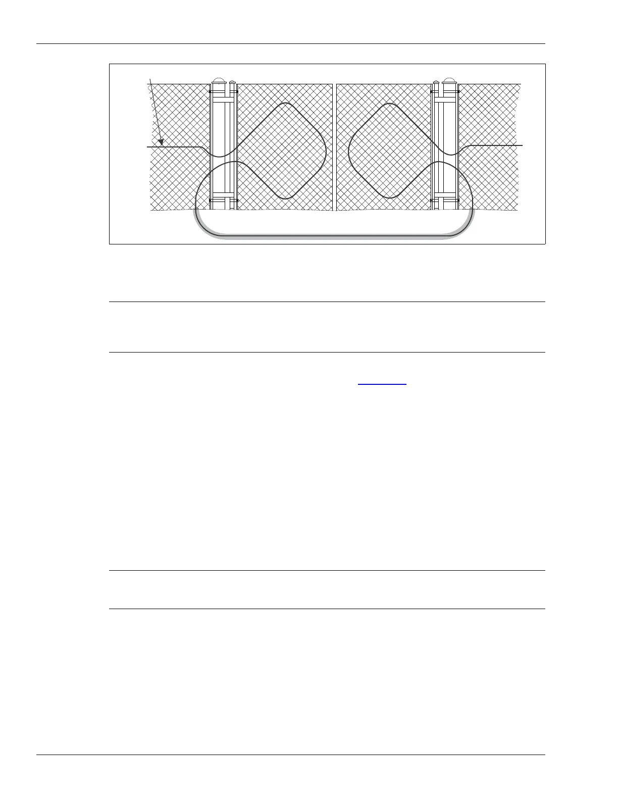
Figure 49: Installing sensor cable on swinging gates
Note The gate disconnect assembly can be used only with sensor cables that
are not carrying power and data to other FlexZone processors.
Otherwise, using the gate disconnect will interrupt power and data to
any processor further down the line.
Note When caps are not in use, they fit into one another for
protection and storage. Cap the connectors when the gate will
be open for extended periods.
sensor cable
protected gates
bypass cable