Installing the FlexZone processor
Page 60 FlexZone Product Guide
Silver Network data path connections
In the standard Silver Network setup, a point to point loop configuration is used for network
communications. Figure 70:
shows the processor to processor network connections for the
EIA-422 and fiber optic communication options. Figure 71:
illustrates an EIA-422 based Silver
Network and Figure 72:
shows a fiber optic based Silver Network. Silver Network’s using Ethernet
communications use a star configuration. Figure 73:
illustrates an Ethernet based Silver Network
(Star configuration) and Figure 74:
shows a Silver Loop + Ethernet configuration in which two
processors are connected to the NMS via Ethernet NICs and a PoE switch, and then communicate
with other processors via the sensor cables.
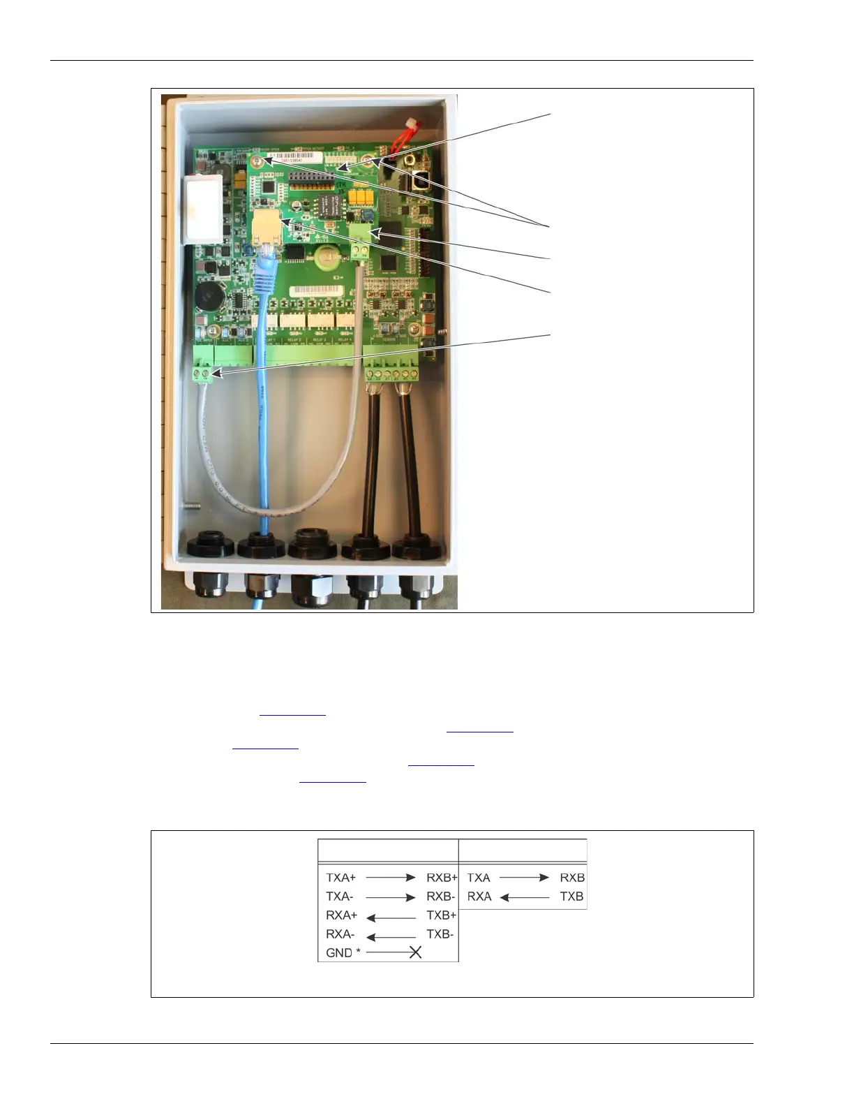
Figure 69: Silver Network Ethernet wiring connections
Figure 70: Silver Network data connections (loop configurations)
expansion header T1
T4 processor power input
(plugs into T2 on processor)
mounting hardware (X 2)
PoE NIC DC output (12 VDC)
Ethernet network connection
(on solder side)
The PoE NIC typically receives power over its
Ethernet connection. It provides power to the
processor through T4, the processor power input.
The processor then supplies power to the NIC
through the expansion header.
If the PoE NIC is not receiving power over its
Ethernet connection, the processor must have
another source of DC power connected to T4.
Connect the PoE NIC ground strap to a ground lug
on the enclosure.
Connect the enclosure ground lug to a nearby
approved earth ground.
EIA-422
Fiber Optic
* Use single point grounding. Connect one end of the cable shield to ground, trim
back the other end and leave it disconnected.