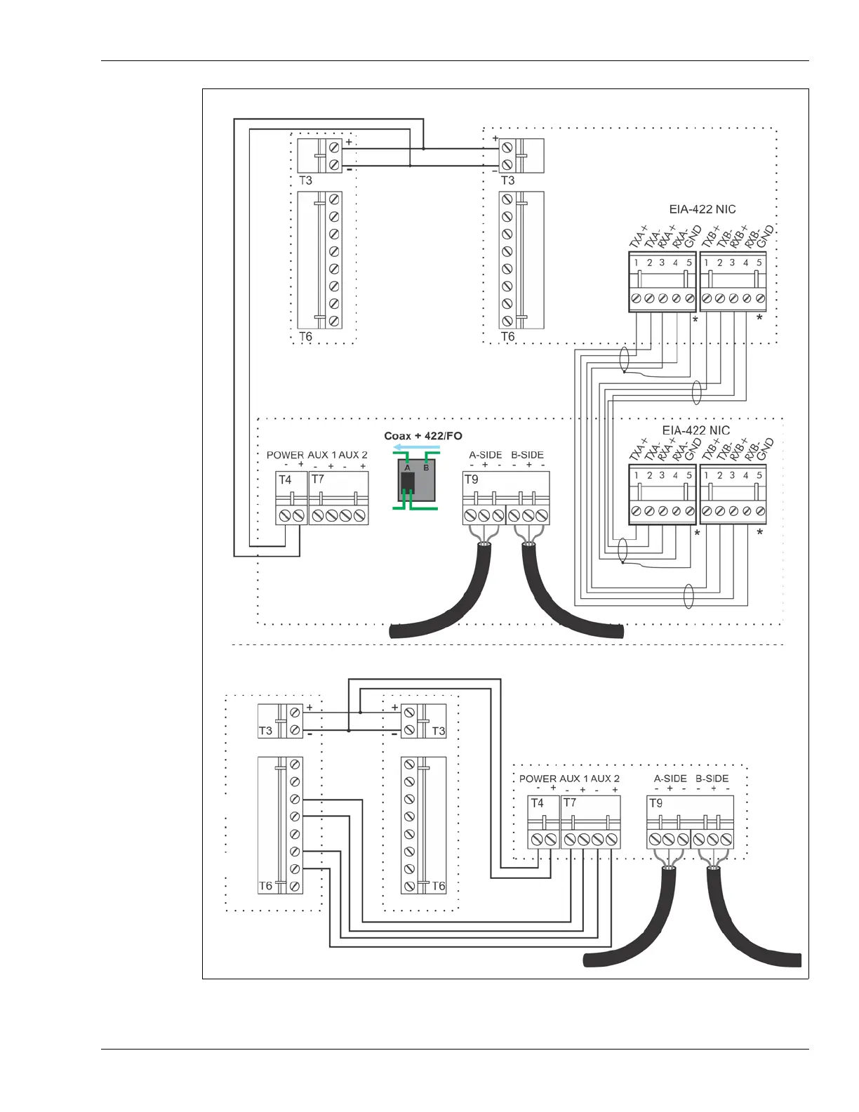
UltraWave Remote control mode Silver Network wiring
UltraWave transmitter
UltraWave receiver
FlexZone processor using power & data via sensor cables
supplying power and data connection to UltraWave sensor
network connection setting
UltraWave Local control mode relay output alarm wiring
O/P 1 Alarm
O/P 2 sup’vn
(N.O. alarm contacts)
FlexZone processor using power & data via sensor cables
supplying power and auxiliary input data connection to
UltraWave sensor
UltraWave transmitter
UltraWave receiver
*
Use single point grounding. Connect one end of
the cable shield to ground. Trim back the other
end and leave it disconnected.