5.17
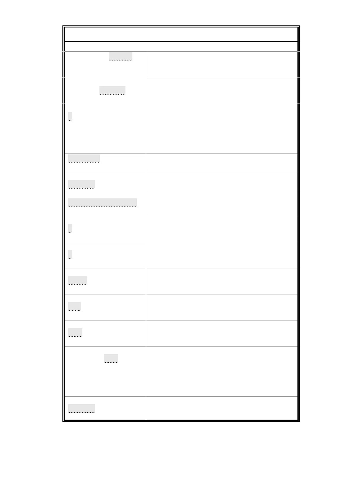
Table 5.14 Setting the serial output communications parameters
L MENU to obtain top level menu
CALIBRATE/SETUP
ALARMS/FAULTS
L < to move the cursor to SETUP (cursor
position shown in inverse video).
L ENTER to choose SETUP.
SET ALARM/ASSIGN
DISPLAY/UTILITY
L ? to move the cursor to DISPLAY
L < to move the cursor to UTILITY
L ENTER to choose UTILITY
ENTER PASSWORD
0000
Both user and supervisor passwords are factory
set to 4000. The cursor will be on digit furthest
to the left initially.
L > > > > to increment the first digit to 4. The
display should now be showing 4000.
L ENTER to enter the password
UTILITY 1
UTILITY 2
L ENTER to choose UTILITY 1
CLOCK/NEW PASS
COMMS/WINDOW
L ? to move the cursor to COMMS
L ENTER to choose COMMS
SET FRAME FREQ
SET COMMS PARMS
L ? to move the cursor to SET COMMS
PARMS
L ENTER to choose SET COMMS PARMS.
SELECT STOP BIT
1/1.5/2
Enter required stop bit.
To change to another selection L = or <
When the value shown is correct L ENTER
SELECT DATA BITS
8/7/6/5
Enter required number of data bits.
To change to another selection L = or <
When the value shown is correct L ENTER
SELECT PARITY
EVEN/ODD/NONE
Enter required parity.
To change to another selection L = or <
When the value shown is correct L ENTER
SELECT BAUD RATE
9K6/4K8/2K4/19K2
Enter required transmission baud rate.
To change to another selection L = or <
When the value shown is correct L ENTER
SELECT CONTROL
DTR/NONE
Enter required hardware hand shaking.
To change to another selection L = or <
When the value shown is correct L ENTER
1,8,E,9K6,DTR
ACCEPT ? YES/NO
Confirm that the specified communications
parameters are correct.
To change to another selection L = or <
When the value shown is correct L ENTER.
New values are applied to the output port at this
time.
CLOCK/NEW PASS
COMMS/WINDOW
To return to measurement display L
MEASURE
 Loading...


