5.10
5.5 External analogue input configuration
The naming and configuration of external analogue inputs is treated identically to
internal process variables. Two external analogue inputs are provided on the
instrument. The process variables associated with these inputs are identified as E1 and
E2 ( the internal transducer process variables are I1 to I4 ). The name and engineering
units for these variables are modified using the UDEF menu entry.
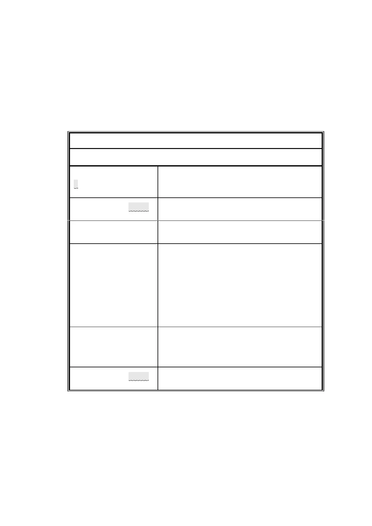
The procedure for configuring the external inputs is given in table 5.8. Definition of the
input scaling ( calibration ) of the external analogue inputs is accomplished via the
MANUAL CAL menu ( see section 4.16 ).
Table 5.8 External analogue input definition
L EDIT to obtain window edit menu
ENTER PASSWORD
0000
To change the value of a digit
L > or ?
To change to another digit L = or <
When the number shown is correct L ENTER
SELECT SCRN/UDEF
DEFINE SCRN/VARS
L < ENTER
SELECT UDEF
E1 |||||| mA
;
L > or ? to select the required external
analogue inputs ( E1 or E2 ) then
L ENTER
E1 COMPONENT
| | | | | |
This entry determines the measurement name
displayed. Any combination of up to 6
characters may be used eg ’STRM 1’. The
character set available is listed in appendix C.
To change a character L > or ?
To change to another character L = or <
When the name is correct L ENTER.
Note any character after the ’|’ symbol is
ignored.
E1 ENG UNIT
| | |
This entry determines the label which follows the
measurement value. It is factory set to mA.
Changing this label does not affect the value
displayed. Change characters as above.
SELECT SCRN/
UDEF
DEFINE SCRN/VARS
L MEASURE to return to measurement display.
 Loading...


