4.11
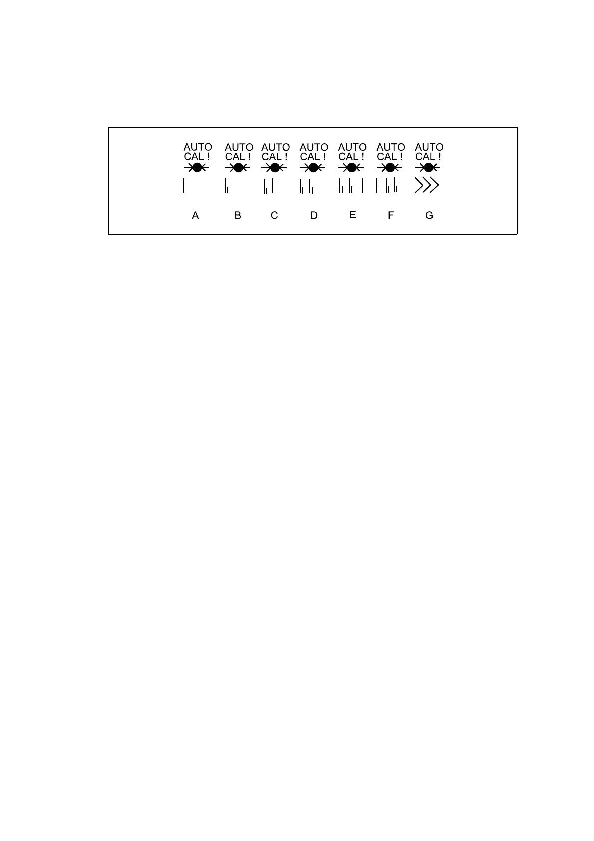
Figure 4.2 Screen icons indicating autocalibration progress
4.8 Monitoring the progress of auto calibration
When the autocalibration facility is initiated an icon appears at the bottom of the
screen. Progress of the autocalibration cycle can be monitored through each of the
phases described in section 4.8 from the appearance of the icon. Figure 4.2 shows
the different icon shapes that indicate the progress of the calibration.
The phase of autocalibration represented by each icon is as follows (the numbers
refer to the events in Fig. 4.1):-
A First calibration gas flushing: DV lag between 1 and 2;
B Measuring first calibration gas: period between 2 and 3;
C Second calibration gas flushing: DV lag between 3 and 4;
D Measuring second calibration gas: period between 4 and 5;
E First calibration gas flushing again: DV lag between 5 and 6;
F Re-measuring first calibration gas: period between 6 and 7;
G Sample gas flushing: DV lag between 7 and 8.
4.9 Auto calibration and auto check setup
The time and date must be correctly set before setting up auto calibration or auto
check (see 3.2 ’Setting time and date’). This will prevent unexpected behaviour due
to incorrect clock set up. The following calibration parameters must be set up when
auto calibration or auto check is to be used:-
’Low’ or ’low and high’ autocalibration/checks
Low sample concentration for each process variable
High sample concentration for each process variable
Auto calibration or auto check
Auto calibration period ie. time between auto calibrations/checks
Date and time of first autocal - note that a time already past will disable
timed autocals
Dead volume ( DV ) lag
Refer to Table 4.7 for the procedures required to set these values.
 Loading...


