4.9
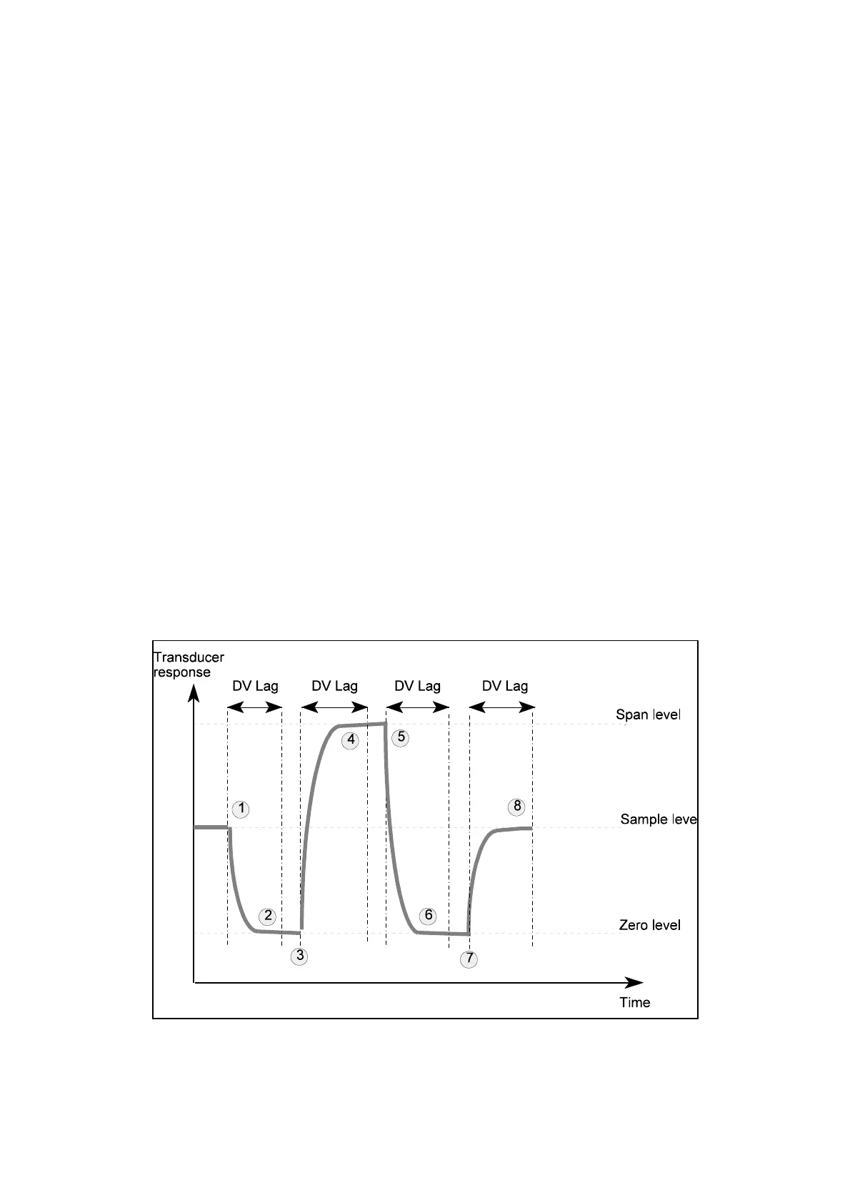
Figure 4.1 Typical autocalibration sequence
4.7 Auto calibration overview
As implied by the name, the auto calibration facility allows the instrument’s calibration
to be updated or checked without user intervention. The auto calibration software
function is only available if an autocalibration hardware option is fitted to the instrument.
Autocalibration facilities are offered to either measure or check the following:-
C Transducer low calibration ( ’zero’ calibration ).
C Transducer low and high calibration ( both ’zero’ and ’span’ ).
In auto calibration two user defined gases ( cal gas 1 and cal gas 2 ) are provided to the
instrument. These gases may be either for low or high calibration of the transducers.
In some cases the same gas may be used for low calibration of one transducer while
being the high calibration of another. The gases are introduced to the analyser in three
phases:-
Phase 1 cal gas 1
Phase 2 cal gas 2
Phase 3 cal gas 1 again.
All of the transducers connected will be autocalibrated simultaneously but the specific
zero or span calculations may occur during different phases.
The following stages define the autocalibration process. The numbers refer to the
stage indications as shown in figure 4.1. This figure shows the transducer response of
a typical transducer during the auto calibration process. In figure 4.1 the first calibration
gas ( cal gas 1 ) is used to measure the transducer zero response and the second
calibration gas ( cal gas 2 ) the span response.
 Loading...


