4
Mechanical installation
Track and vehicle geometry
Assembly and Operating Instructions – MAXO-MS/M/SM-GIOP Sensor Module
15
4 Mechanical installation
4.1 Track and vehicle geometry
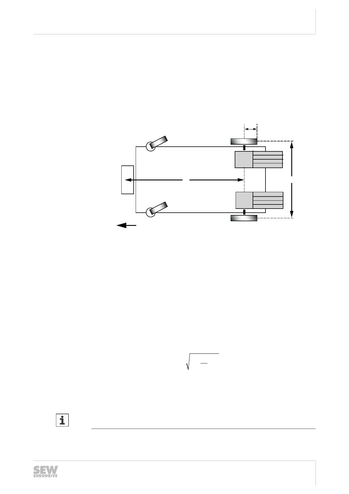
4.1.1 Distance designation
The following figure shows the vehicle from below (in the direction of travel) with the
designation of the distances:
34148228235
SM Sensor module
R Distance R between the sensor module (SM) and the steered axis
M Motor
A Distance of the two drive wheels
r
RAD
Tire radius
These parameters are required for configuring the sensor module. They also apply to
slightly different vehicle designs with swivel wheel suspension.
An advantage of vehicles with swivel wheel suspension is that they run more smoothly
during operation.
4.1.2 Distance between the sensor module and the steered axis
The distance R between the sensor module and the steered drive axis must be at
least as large as the result calculated using the following formula:
R =
min max
( . )1 6
2
s
m
A v× ×
2561101579
v
max
Maximum travel speed in m/s
INFORMATION
This condition also applies to vehicle designs with swivel wheel suspension.
26868113/EN – 03/2021