4
Mechanical installation
Project planning notes on inductive track guidance
Assembly and Operating Instructions – MAXO-MS/M/SM-GIOP Sensor Module
19
4.4 Project planning notes on inductive track guidance
4.4.1 Distances for line cable routing
Inductive track guidance is used with line cables (round or wedge-shaped) that are
routed at a distance of 140mm.
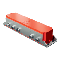
The following figure shows the distances that must be observed when mounting the
sensor module using a round line cable as an example:
5 mm
25 mm 25 mm
140 mm
25 mm
[1]
[2]
[3]
34055863051
[1] Sensor module
[2] Line cable (round design)
[3] Hall floor
Install the sensor module [1] in such a way that the distance between hall floor [3] and
bottom of the housing is 25mm. This value applies when the line cable [2] is routed so
that the top edge of the cable is 5mm below the surface of the hall floor.
When routing the line cable, ensure that the distance between the top edge of the line
cable and the surface of the hall floor is kept constant along the entire track. Before
routing the line cable, exactly determine the thickness of the surface covering above
the line cable. Avoid lateral deviations when routing the line cable because the track-
guided vehicle follows the routed cable pair exactly.
A constant height must be observed between the sensor module and the line cable.
Deviations of ±3 mm in the height from the measuring system to the line cable pair
leads to a track deviation of ±2mm.
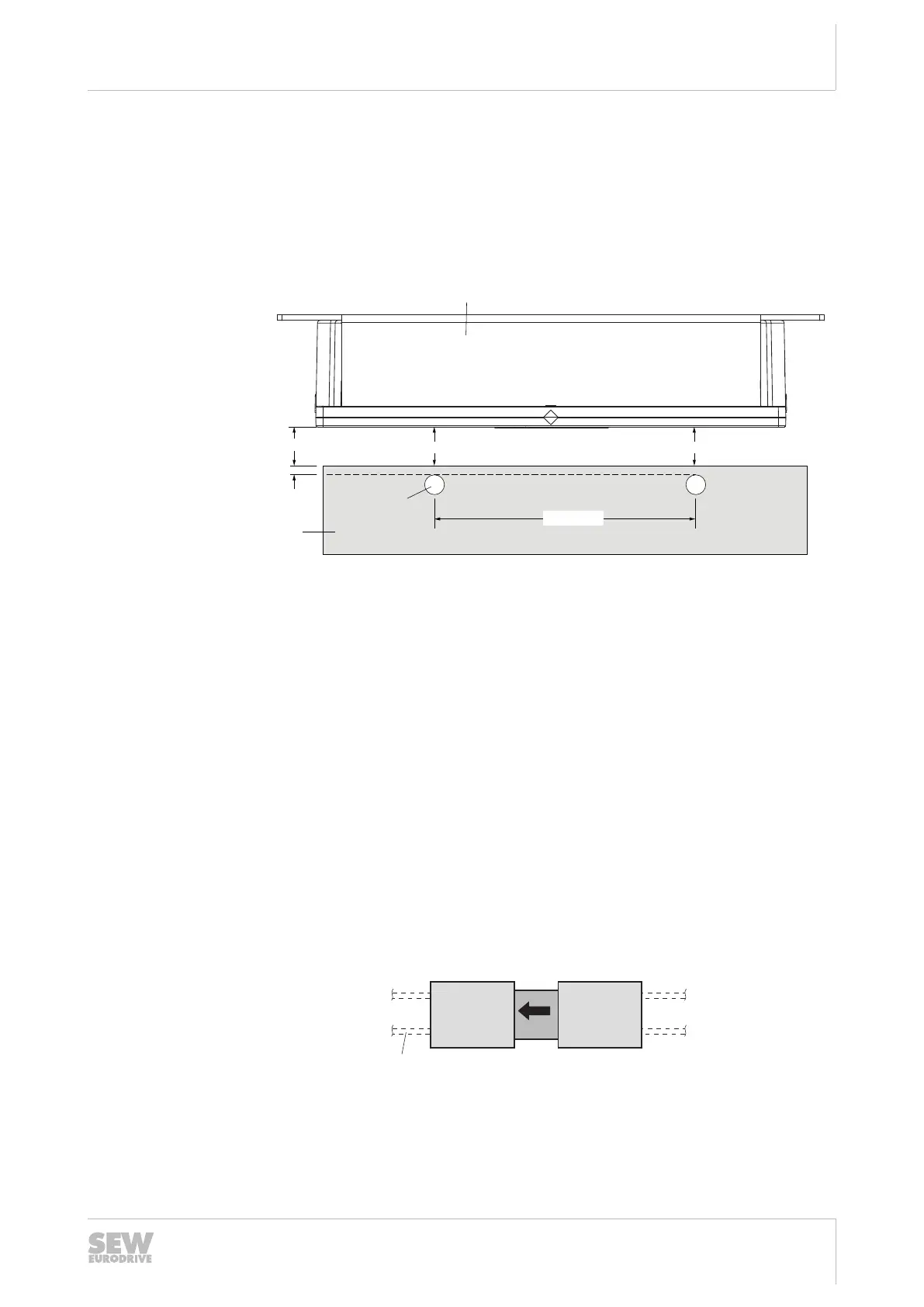
4.4.2 Distance to pick-ups
The following figure shows the installation of the sensor module between 2 flat
MOVITRANS
®
THM10E pick-ups:
34064605195
[1] MOVITRANS
®
THM10E pick-up
[2] Sensor module
[3] Line cable
Observe the following notes for installation:
26868113/EN – 03/2021