4
Mechanical installation
Minimum clearances
Assembly and Operating Instructions – MAXO-MS/M/SM-GIOP Sensor Module
17
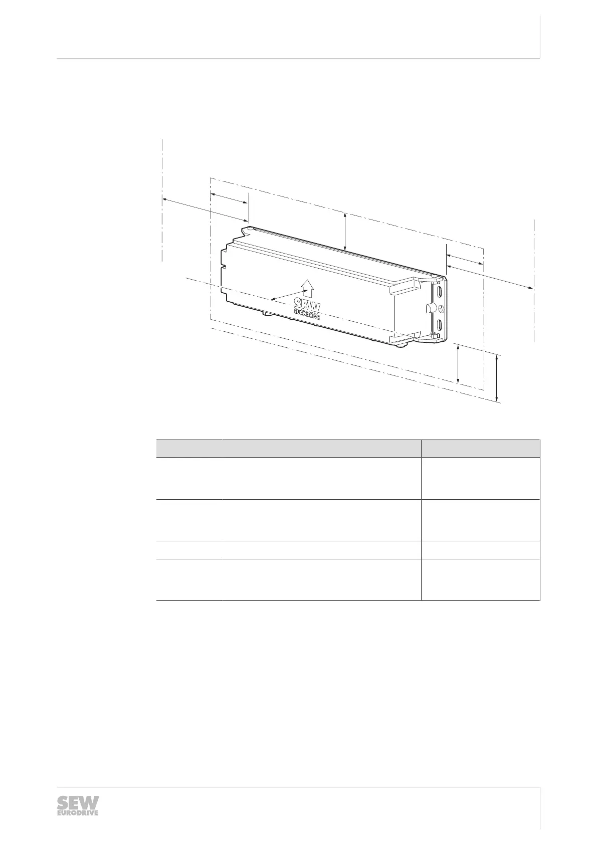
4.2 Minimum clearances
SEW‑EURODRIVE recommends observing the following clearances when mounting
the device:
33693137803
The following table lists the minimum clearances:
Clearance Function Clearance
A Distance to metallic components. This way,
you can avoid a reduction of the range
when reading an RFID transponder.
≥ 50mm
B Distance to metallic components. Metallic
components prevent the sensor technology
from functioning correctly.
≥ 125mm
C Space for cable entry and plug connectors ≥ 60mm
D Distance to floor to avoid collisions with
obstacles and to ensure proper operation
of the sensor technology
≥ 25mm
4.3 Travel direction
It is important that you align the sensor module correctly in reference to the direction
of travel. To help you do this, an arrow is printed on the top of the housing to indicate
the direction of travel.
The sensor module must always be in front of the steered axis. This means a track
point is crossed first by the sensor module and then by the steered axis.
26868113/EN – 03/2021