MX-5001N ADJUSTMENTS 5 – 48
5) Image loss adjustment
When the adjustment item of the image loss below is set to the
default value, it is adjusted to the standard state. If it is not in
the below standard state, or when it is set to a desired value,
change these adjustment items.
Void area: 3.0mm, Image loss: 3.0mm
When the adjustment value is increased, the image loss is
increased. When the adjustment value is decreased, the
image loss is decreased.
When the adjustment value is changed by 1, the void area is
changed by 0.1mm.
18-B Document scan position adjustment
(RSPF mode)
18-C Document scan position adjustment
(DSPF mode)
Document scan start position adjustment
(Scanner reading position adjustment when scanning the front sur-
face in the RSPF/DSPF mode) (RSPF/DSPF mode)
This adjustment must be performed in the following cases:
* When the scan control PWB is replaced.
* When the EEPROM on the scan control PWB is replaced.
* When the scanner (reading) section is disassembled.
* When the scanner (reading) section is replaced.
* When U2 trouble occurs.
* When the RSPF/DSPF section is disassembled.
* When the RSPF/DSPF unit is replaced.
This simulation is to adjust the scanner reading position when
scanning the front surface in the RSPF/DSPF mode.
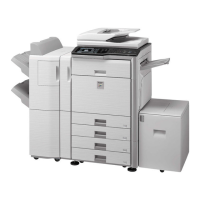
If this adjustment is made improperly, the scanner stop position is
shifted to the specified position and a shade of the document table
may be reflected on the lead edge section of the scan image in the
RSPF/DSPF (front surface) mode.
a. Adjustment procedures
1) Make a copy in the RSPF/DSPF (front surface) mode, and
check for any shade on the lead edge section of the copy
image.
If there is any shade of the document table on the lead edge
section of the copy image, perform the following procedures.
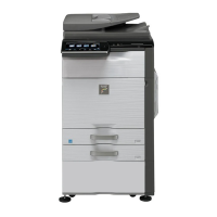
2) Enter the SIM53-8 mode, and press [MANUAL] key.
3) Enter an adjustment value with 10-key, and press [OK] key.
When the set value is increased, the distance from the home
position to the RSPF/DSPF scanning position is increased.
When the set value is changed by 1, the scanning position is
changed by 0.1mm.
Perform the procedures of 1) - 3) until a satisfactory result is
obtained.
NOTE: After execution of this adjustment, be sure to execute
ADJ18D Copy image position and image loss adjustment
(DSPF mode) and ADJ18E Copy image position and
image loss adjustment (DSPF mode).
18-D Copy image position, image loss
adjustment (RSPF mode)
18-E Copy image position, image loss
adjustment (DSPF mode)
This adjustment must be performed in the following cases:
* When the scan control PWB is replaced.
* When the EEPROM on the scan control PWB is replaced.
* When the scanner (reading) section is disassembled.
* When the scanner (reading) unit is replaced.
* When U2 trouble occurs.
* When the RSPF/DSPF section is disassembled.
* When the RSPF/DSPF unit is replaced.
Display
/Item
Content
Adjust
ment
range
De-
fault
Standard
adjustment
value
LEAD Image loss
adjustment
Lead edge
image loss
adjustment
0 - 99 30 3.0
± 1.0mm
SIDE Side image
loss adjustment
0 - 99 20 2.0
± 1.0mm
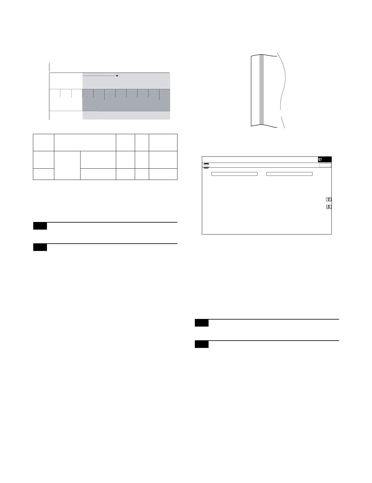
5mm
10mm
4
32
1
Paper lead edge
Maginification ratio : 400%
Copy area
Image area
Papar lead edge
Shadow image of RSPF
ǂǂǂ6,08/$7,21ǂǂ12
&/26(
7(67
63)6&$11,1*326,7,21$'-8670(17
$872 0$18$/