MX-5001N ADJUSTMENTS 5 – 49
NOTE: To execute this adjustment, the following items must have
been properly adjusted.
b. Adjustment procedures
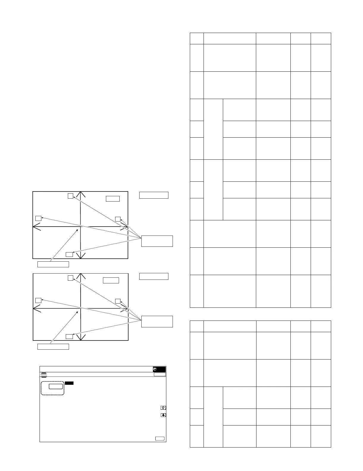
1) Prepare the adjustment chart.
The adjustment chart can be made by the following proce-
dures.
Use A4 (11" x 8.5") paper and draw arrow marks vertically and
horizontally on the front and the back surfaces.
At the same time, put marks of the lead edge, the trail edge,
the front end, and the rear end as well as the identification
marks of the front surface and the back surface.
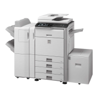
2) Enter the SIM50-6 mode.
SIM50-6
(DSPF)
(RSPF)
ADJ 15 Scan image magnification ratio adjustment
(RSPF/DSPF mode)
ADJ 16B RSPF mode off-center adjustment
ADJ 16C DSPF mode off-center adjustment
ADJ 15A Scan image magnification ratio adjustment
(Main scanning direction) (RSPF mode)
ADJ 15C Scan image magnification ratio adjustment
(Main scanning direction) (DSPF mode)
ADJ 15B Scan image magnification ratio adjustment
(Sub scanning direction) (RSPF mode)
ADJ 15D Scan image magnification ratio adjustment
(Sub scanning direction) (DSPF mode)
ADJ 17 Print area (Void area) adjustment
(Print engine section)
ADJ 18B Document scan position adjustment (RSPF mode)
ADJ 18C Document scan position adjustment (DSPF mode)
F
L
R
FACE
BACK
R
T
F
L
T
Front surface
Back surface
Draw arrows.
Draw arrows.
Put the position
marks.
Put the position
marks.
ǂǂǂ6,08/$7,21ǂǂ12
&/26(
7(67
/($'('*($'-8670(179$/8(63)
$˖
˷˹
˖6,'(
$˖
˖6,'(
%˖
˖/($'B('*(6,'(
&˖
˖)5217B5($56,'(
'˖
˖/($'B('*(6,'(
)˖
˖75$,/B('*(6,'(
(˖
˖)5217B5($56,'(
*˖
˖75$,/B('*(6,'(
+˖
˖2)6(7B63)
,˖
˖2)6(7B63)
-˖
˖6&$1B63(('B63)
.˖
2.
Item Display Content
Setting
range
Default
value
A SIDE1 Front surface
document scan
position
adjustment
(CCD)
1 - 99 50
B SIDE2 Back surface
document scan
position
adjustment
(CCD)
1 - 99 50
CImage
loss
amount
setting
SIDE1
LEAD_EDGE
(SIDE1)
Front surface
lead edge
image loss
amount setting
0 - 99 20
D FRONT_REAR
(SIDE1)
Front surface
side image loss
amount setting
0 - 99 20
E TRAIL_EDGE
(SIDE1)
Front surface
rear edge
image loss
amount setting
0 - 99 30
FImage
loss
amount
setting
SIDE2
LEAD_EDGE
(SIDE2)
Back surface
lead edge
image loss
amount setting
0 - 99 30
G FRONT_REAR
(SIDE2)
Back surface
side image loss
amount setting
0 - 99 20
H TRAIL_EDGE
(SIDE2)
Back surface
rear edge
image loss
amount setting
0 - 99 20
I OFSET_SPF1 RSPF front
surface
document off-
center
adjustment
1 - 99 50
J OFSET_SPF2 RSPF back
surface
document off-
center
adjustment
1 - 99 50
K SCAN_SPEED_SPF1 RSPF
document front
surface
magnification
ratio adjustment
(Sub scan)
1 - 99 50
Item Display Content
Setting
range
Default
value
A SIDE1 Front surface
document scan
position
adjustment
(CCD)
1 - 99 50
B SIDE2 Back surface
document scan
position
adjustment
(CCD)
1 - 99 50
CImage
loss
amount
setting
SIDE1
LEAD_EDGE
(SIDE1)
Front surface
lead edge
image loss
amount setting
0 - 99 20
D FRONT_REAR
(SIDE1)
Front surface
side image loss
amount setting
0 - 99 20
E TRAIL_EDGE
(SIDE1)
Front surface
rear edge
image loss
amount setting
0 - 99 30