MX-5001N ADJUSTMENTS 5 – 50
* Item A, B: When the adjustment value is increased, the scan
timing is delayed.
* Item C - H: When the adjustment value is increased, the
image loss is increased.
* Item A - H: 1 step = 0.1mm change
* The SPF rear edge image loss is provided for countermea-
sures against shades.
NOTE: When [CLOSE] key is pressed in this simulation mode, the
machine goes into the normal operation mode. Under this
state, copy check can be normally performed. When the
system key is pressed, the machine returns to the simula-
tion mode.
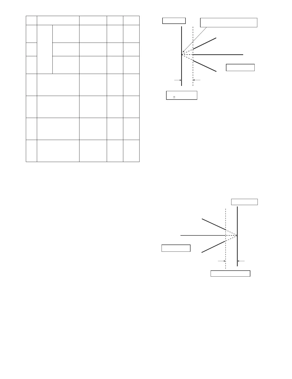
(Lead edge image loss adjustment)
1) Set the lead edge image loss adjustment values (LEAD EDGE
(SIDE1/SIDE2)) on the front surface and the back surface to
the following values.
(Standard set value)
LEAD EDGE(SIDE 1):
30 Lead edge image loss set value (Front surface)
LEAD EDGE(SIDE 2):
30 Lead edge image loss set value (Back surface)
(When the set value is increased, the lead edge image loss is
increased.)
(Change for change in the set value: 0.1mm/step)
2) Make a duplex copy in 100% in the RSPF/DSPF mode. Check
to confirm that the lead edge image loss is within 3.0±1.0mm
on the front surface and the back surface. The paper lead
edge must be aligned with the presumed image lead edge.
If the above condition is not satisfied, perform the following
procedure.
3) Enter the adjustment value of SIDE1/SIDE2 with 10-key, and
press [OK] key.
Adjust so that the paper lead edge is aligned with the pre-
sumed image lead edge.
SIDE1: Front surface lead edge scan position adjustment
SIDE2: Back surface lead edge scan position adjustment
(When the adjustment value is increased, the print image posi-
tion is shifted to the delaying direction for the paper.)
(Change for change in the set value: 0.1mm/step)
Perform the procedures of 2) - 3) until a satisfactory result is
obtained.
(Rear edge image loss adjustment)
1) Make a duplex copy in 100% in the RSPF/DSPF mode. Check
to confirm that the rear edge image loss is 2.0 - 5.0mm on the
front surface and the back surface.
If the above condition is not satisfied, perform the following
procedure.
2) Enter the adjustment value of TRAIL EDGE (SIDE1/SIDE2)
with 10-key, and press [OK] key.
TRAIL EDGE (SIDE 1): Rear edge image loss adjustment
value (Front surface)
TRAIL EDGE (SIDE 2): Rear edge image loss adjustment
value (Back surface)
(When the adjustment value is increased, the rear edge image
loss is increased.)
(Change for change in the set value: 0.1mm/step)
Perform the procedures of 1) - 2) until a satisfactory result is
obtained.
F Image
loss
amount
setting
SIDE2
LEAD_EDGE
(SIDE2)
Back surface
lead edge
image loss
amount setting
0 - 99 20
G FRONT_REAR
(SIDE2)
Back surface
side image loss
amount setting
0 - 99 20
H TRAIL_EDGE
(SIDE2)
Back surface
rear edge
image loss
amount setting
0 - 99 30
I OFSET_SPF1 RSPF front
surface
document off-
center
adjustment
1 - 99 50
J OFSET_SPF2 RSPF back
surface
document off-
center
adjustment
1 - 99 50
K SCAN_SPEED_SPF1 RSPF
document front
surface
magnification
ratio (Sub scan)
1 - 99 50
L SCAN_SPEED_SPF2 RSPF
document back
surface
magnification
ratio (Sub scan)
1 - 99 50
Item Display Content
Setting
range
Default
value
Paper lead edge
Copy image
Image loss
3.01.0mm
The paper lead edge must be aligned with
the image lead edge.
Paper rear edge
Copy image
Image loss 2.0 - 5.0mm