MX-M260/M310/M260N/M310N EXTERNAL VIEW AND INTERNAL STRUCTURE 4 - 8
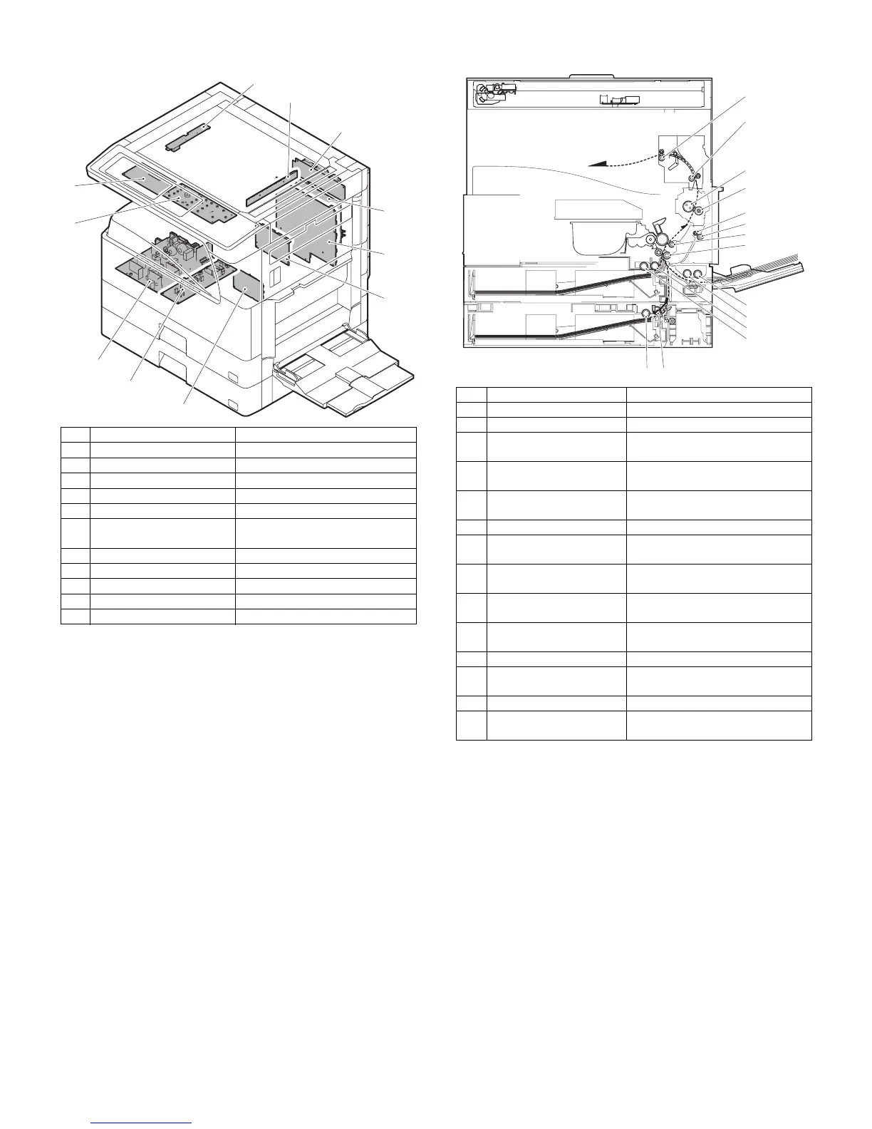
11. PWB 12. Roller
No. Name Function and operation
1 Inverter PWB Copy lamp control
2 CCD PWB For image scanning (read)
3 Option connector PWB
4 IMC PWB Image process
5 MCU PWB Main unit control
6 Mother board Connection with FAX PWB and
PCL PWB
7 Tray interface PWB 2nd tray control
8 DC power supply PWB DC voltage control
9 High voltage PWB High voltage control
10 KEY PWB
11 OPU PWB Operation panel control
1
2
3
4
5
6
7
9
8
10
11
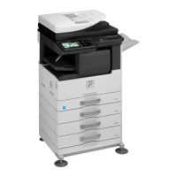
No. Name Function and operation
1 Paper exit roller Paper exit roller
2 Transport roller Paper transport roller
3 Upper heat roller Fuses toner on paper.
(with the Teflon roller)
4 Lower heat roller Fuses toner on paper.
(with the silicone rubber roller)
5 DUP transport follower
roller
Duplex paper transport
6 DUP transport roller Duplex paper transport
7 Transport roller Transfer images on the drum onto
paper.
8 Resist roller Synchronize the paper lead edge
with the image lead edge.
9 Manual paper feed roller Picks up papers in manual paper
feed port.
10 Manual feed transport
roller
Transports paper from the manual
paper feed port.
11 1st tray pick-up roller Picks up paper from the tray.
12 1st tray paper feed roller Transports the picked up paper to
RESIST section.
13 2nd tray pick-up roller Picks up paper from the tray.
14 2nd tray paper feed roller Transports the picked up paper to
RESIST section.
1
2
3
4
5
6
7
8
9
10
11
12
1314