MX-M260/M310/M260N/M310N ADJUSTMENTS 5 - 3
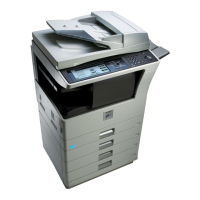
6) Measure the distance H between the paper lead edge and the
image print start position. Set the image print start position set
value again.
• 1 step of the set value corresponds to about 0.127mm shift.
• Calculate the set value from the formula below.
99 – H/0.127 (mm) = Image print start position set value
<H: Print start position measurement value (mm)>
∗ Fit the print edge with the paper edge, and perform the lead
edge adjustment.
Example:99 – 5/0.127 = 99 – 39.4 = about 59
Note : FIf the set value is not obtained from the above formula, per-
form the fine adjustment.
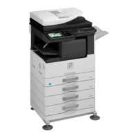
7) Execute SIM 50-1-2 to adjust the main tray lead edge void.
• 1 step of the set value corresponds to about 0.127mm shift.
• Calculate the set value from the formula below.
B/0.127 (mm) = Lead edge void adjustment value
<B: Lead edge void (mm)>
Example: When setting the lead edge void to 2.5mm:
2.5 /0.127 = about 20
<Adjustment specification>
[H: Print start position measurement value (mm),
B: Lead edge void (mm)]
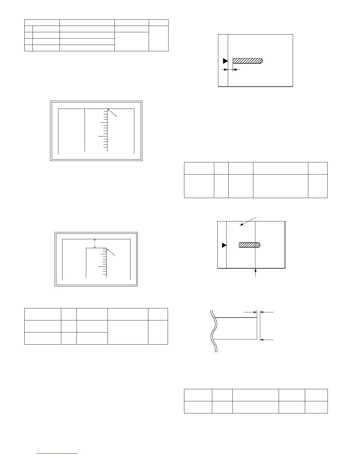
(2) RSPF image lead edge position adjustment
1) Set a scale on the OC table as shown below.
Note: Since the printed copy is used as a test chart, put the scale in
paralleled with the edge lines.
2) Make a copy, then use the copy output as an original to make an
RSPF copy again.
3) Check the copy output. If necessary, perform the following adjust-
ment procedures.
4) Execute SIM 50-6.
5) Set the RSPF lead edge position set value so that the same image
is obtained as that obtained in the previous OC image lead edge
position adjustment.
<Adjustment specification>
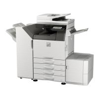
(3) Rear edge void adjustment
1) Set a scale as shown in the figure below.
2) Set the document size to A4 (8.5" x 11"), and make a copy at
100%.
3) If an adjustment is required, follow the procedures below.
4) Execute SIM 50-1 and set the density mode to DEN-B. The cur-
rently set adjustment value is displayed.
5) Enter the set value and press the start key.
The correction value is stored and a copy is made.
<Adjustment specification>
Item Content Setting range Default
1TRAY1
1st tray 0-99
53
2OPTION
Option tray
1-99
3MANUAL
Manual feed
4DUPLEX
Back print
Adjustment
mode
SIM Set value Spec value
Setting
range
Main tray lead
edge void
50-1
-2
B/0.127 Lead edge void:
1 – 4mm
Image loss: 3mm
or less
1 – 99
Print start
position
50-5 99 – H/0.127
5
10
0mm
0mm
5
10
2.5mm
2.5mm
Adjustment
mode
SIM Set value Spec value
Setting
range
RSPF
image lead
edge
position
50-6 1 step:
0.127mm
shift
Lead edge void:
1 – 4mm
Image loss: 3mm or less
1 – 99
Adjustment
mode
SIM Set value
Spec
value
Setting
range
Rear edge
void
50-1-6
1 step: 0.127mm
shift
4mm or
less
1 – 99
A4 (8.5" x 11")
Paper rear edge
Void amount (Standard value: 4mm or less)
Scale image
Paper rear edge