Application parameter group
PARAMETER DESCRIPTION 150
1. Whether the remote setting function is valid and whether the frequency setting storage function in the remote
setting mode is used or not are determined by 10-11.
Set 10-11=1~3 (valid remote setting function), the function of terminal RM, RH and RL will be changed to
acceleration (RH), deceleration (RM) and clear (RH).See the following figure:
Inverter
Forward rotation
Acceleration
Deceleration
Clear
STF
RH
RL
RM
SD
10
2
5
2. In the remote setting, the output frequency of the inverter is: (frequency setting by RH/RM operation +
external setting frequency other than multi-speeds/PU setting frequency)
Frequency setting storage condition
The frequency setting storage function is to store the remote-set frequency (frequency set by RH/RM operation) in
memory (EEPROM). Once the power supply is cut off and turned on again, the inverter can start running again at
the remote-set frequency (10-11=1).
<Frequency setting storage condition>
1. It is the frequency when the start signal (STF/STR) is “off”.
2. When the signal RH (acceleration) and RM (deceleration) are both “off” and “on”, the remote-set frequency is
stored every minute. (Current frequency set value and the last frequency set value are compared ever minute.
If they are different, then the current frequency set value is written in the memory. If RL is on, write-in will be
unavailable).
Note: 1. The frequency can be varied by RH (acceleration) and RM (deceleration) between 0 and (the maximum
frequency – frequency set by the main speed). The output frequency is limited by 01-00.
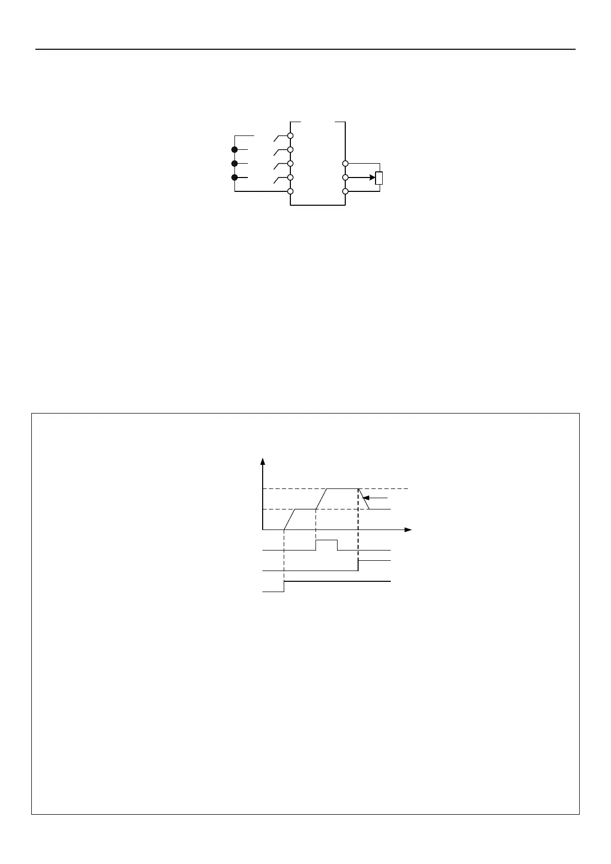
P.1
Output
frequency
Setting frequency
0Hz
Hz
AccelerationRH
DecelerationRH
Forward rotation
(STF)
ON
ON
ON
2. When the acceleration or deceleration signal is “on”, the acceleration / deceleration time will be determined by
the set value of 01-06 (the first acceleration time) and 01-07 (the first deceleration time).
3. When RT signal is “on” and 01-22≠99999 (the second acceleration time), 01-23≠99999 (the second
deceleration time), the acceleration / deceleration time will be determined by the set value of 01-22 and 01-23.
4. When the start signal (STF/STR) is “off” and RH (acceleration) / RM (deceleration) is “on”, the target frequency
will also change.
5. When the start signal (STF/STR) becomes “off”, make the frequency setting storage function invalid (10-11=2,
3) if the frequency has to be changed continuously through RH/RM. If the frequency setting storage function is
valid (10-11=1), the life of EEPROM will be shortened by frequent EEPROM data writing.
6. RH, RM and RL mentioned in this chapter are function names of “multi-function digital input terminal”. If the
functions of the terminals are changed, other functions are likely to be affected. Please verify the functions of
the terminals before changing the options and functions of the multi-function digital input terminal (please refer
to 03-00, 03-01, 03-03 and 03-04. For wiring, please refer to Section 3.7.
 Loading...