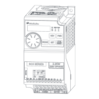
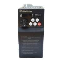
Basic operation procedures for different modes
PRIMARY OPERATION 41
4.3.9 Basic operation procedures for combined mode 5 (00-16(P.79)=8)
• In Combined Mode 5, indicating lamp will light up.
Note: For selecting and switching the operation mode, please refer to Section4.2.
•The target frequency of the inverter is set byoperation panel:
• When RL, RM, RH and REX of multi-speed stage levels are “on”, the target frequency is determined by combination of
multi-speed stage levels (please refer to04-00~04-02/P.4~P.6, 03-00~03-01/P.83~P.84,03-03~03-04/P.80~P.81)。
•When external JOG is “on”, the target frequency is determined by 01-13(P.15). Acceleration / deceleration time is set by
the value of 01-14(P.16).
•The inverter starting is activated by the external forward and reverse terminals.
Note: 1. For detailed operation flow for the monitor mode, please refer to Section 4.2.3.
2. While the motor is running, the user can enter into the frequency setting mode to change the target frequency for
regulating the motor speed.
•When the digital input terminals stop the output signals, the motor will decelerate until it comes to a full stop.
• Indicating lamp will not turn off until the inverter stops the output.

 Loading...


