Appendix E Maintenance and Inspection
Mobile DaRt Installation Manual
E-xvii
i
E.7 Adjustment of Collimator lamp voltage
1. Basical adjustment of Collimator lamp voltage
Collimator lamp voltage can be adjusted by adjusting pulse width on MUX
CHARGE-04A PCB. Detailed procedure is as follows,
(1) Disconnect the connector JCH2 form MUX CHARGE-04A PCB for
preventing lamp from getting excessive voltage during adjustment.
(2) Connect oscilloscope to CP17 (IC M8 pin No.1) and GND on MUX
CHARGE-04A PCB.
(3) Turn on the unit. (Turn on the key switch.)
(4) Press the Collimator lamp switch and execute (5) in 30 seconds.
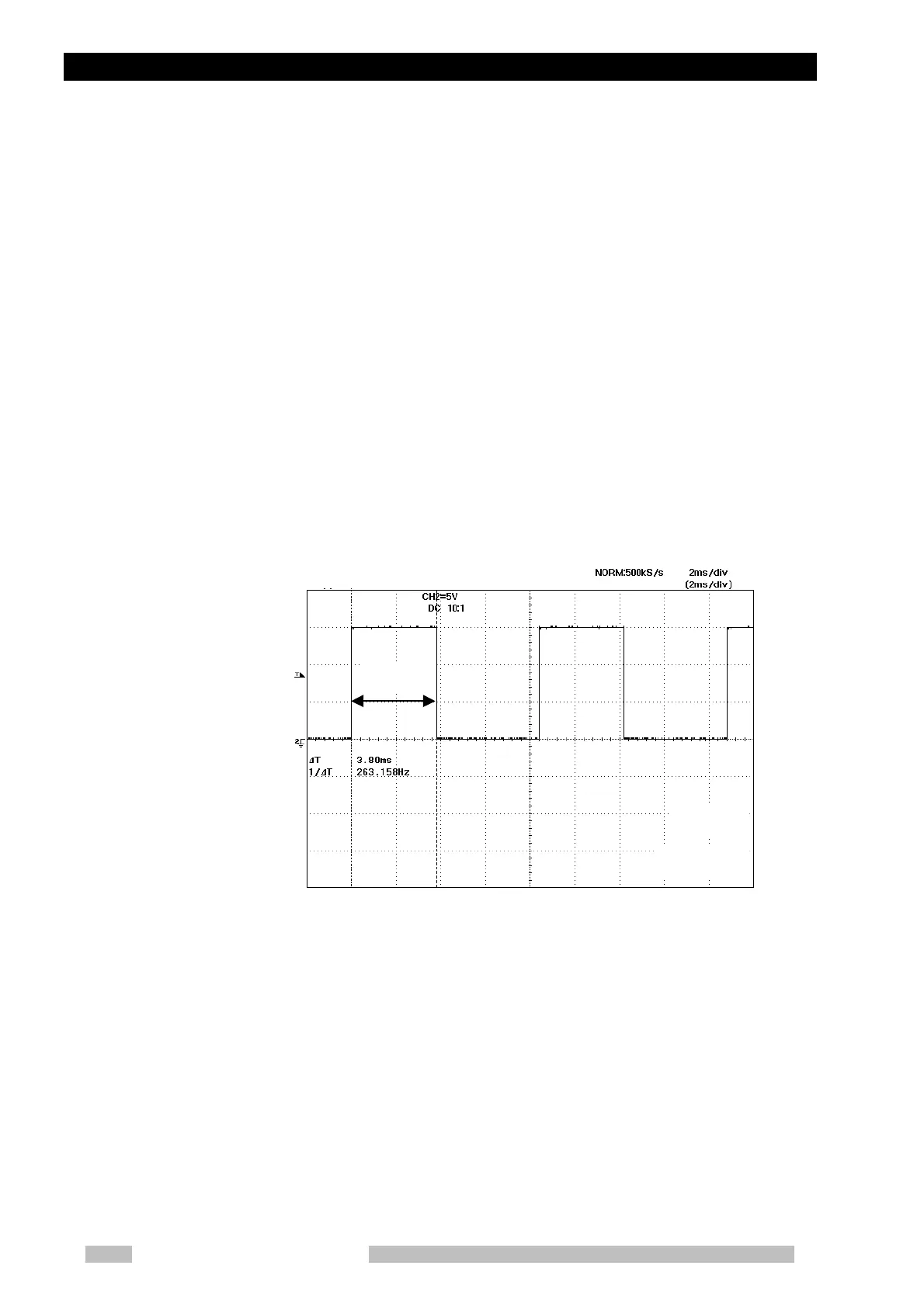
(5) Adjust the VR1 [LAMP] on MUX CHARGE-04A PCB so that the pulse
width (+15V level) is 3.8ms (+/- 0.1ms).
See the below figure.
(6) Turn off the unit. (Turn off the key switch.)
(7) Connect the connector JCH2 to MUX CHARGE-04A PCB that was
disconnected in (1).
3.8ms
5V/div
2ms/div
 Loading...