Operating Instructions Chapter 3
C4000
Product description
8 009 221/16-11-00 © SICK AG • Safety Systems • Germany • All rights reserved 11
3.2.2 The light curtain principle
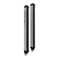
The safety light curtain C 4000 consists of a sender and a receiver (figure 1). Between
these two units is the protective field, defined as the protective field height and the protec-
tive field width.
The construction size height determines the height of the protective field of the appropriate
system. The upper and lower limit of the protective field is shown by markings on the profile
sections.
The width of the protective field is derived from the length of the light path between sender
and receiver and must not exceed the maximum rated width of the protective field (see
“Technical specifications” on page 43).
Sender and receiver automatically synchronize themselves optically. An electrical connec-
tion between both these components is not required.
The C 4000 is modular in structure. All optical and electronic components and assemblies
are housed in a slim and torsionally rigid housing.
3.2.3 Cascading
To provide an effective point-of-operation guard, a maximum of three C 4000 can be con-
nected in series for cascading configuration. The device connected to the control cabinet
is the main sensor, called Host. The subsequent sensors are called Guests (cf. figure 1 on
page 10).
Benefits of cascading
· No additional external circuitry required
· Resolution and protective field height may differ among the individual systems
Limits of cascading
· The maximum protective field width must be guaranteed for each individual system!
· The maximum total number of beams must be 480 beams in non-coded operation,
and a maximum of 405 beams in coded operation.
· The maximum cable length between two cascaded systems must not exceed 3 meters.

 Loading...