Operating Instructions Chapter 3
C4000
Product description
8 009 221/16-11-00 © SICK AG • Safety Systems • Germany • All rights reserved 15
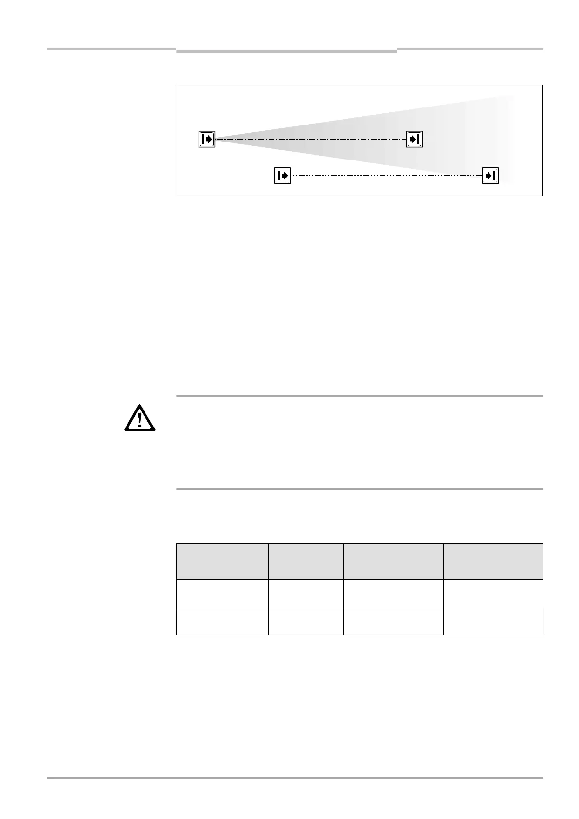
Fig. 6: Schematic layout of the
beam coding
Notes · Beam coding increases the availability of the protected machine. Beam coding also en-
hances the resistance to optical interference such as welding sparks and similar.
· In a cascaded system, host and guest can be operated only with the same beam coding.
· Beam coding will increase the response time of the system. This may also change the re-
quired safety distance. For details refer to chapter 4.1 “Determining the safety distance”
on page 22.
· After activating the system, sender and receiver will briefly display the coding.
· If operated with beam coding, the number of beams in cascaded systems must not ex-
ceed 405 beams.
n
Device symbol C 4000 receiver or sender, context menu Configuration draft, Edit, file card
General, option Beam coding.
3.4.4 Scanning range
WARNING
a
Match the scanning range with the protective field width!
The scanning range of the system (host, guest 1 and guest 2) must be adapted to the width
of the protective field.
· If the scanning range is too small, the light curtain will not change to green.
· If the scanning range is too great, the light curtain may malfunction. This would mean that
the user/operator is at risk.
Note If you are using the additional front screen (see page 56) available as an accessory, the
useful scanning range will be reduced by 8% for each additional front screen.
The available settings depend on the physical resolution of the system:
n
Device symbol C 4000 receiver or sender, context menu Configuration draft, Edit, file card
General, option Scanning range.
Code 1
Code 2
Physical resolution Selectable
scanning ranges
Scanning range with
1 additional front
screen
Scanning range with
2 additional front
screens
14 mm 0-2.5 m
2-6 m
0-2.3 m
1.8-5.5 m
0-2.1 m
1.7-5 m
20 mm, 30 mm,
40 mm
0-6 m
2.5-19 m
0-5.5 m
2.3-17.4 m
0-5 m
2.1-16 m
a
.
:
ys
ca
reso
ut
on an
canning range

 Loading...
