Operating Instructions Chapter 10
C4000
Technical specifications
8 009 221/16-11-00 © SICK AG • Safety Systems • Germany • All rights reserved 49
10.4.2 Cascadable system
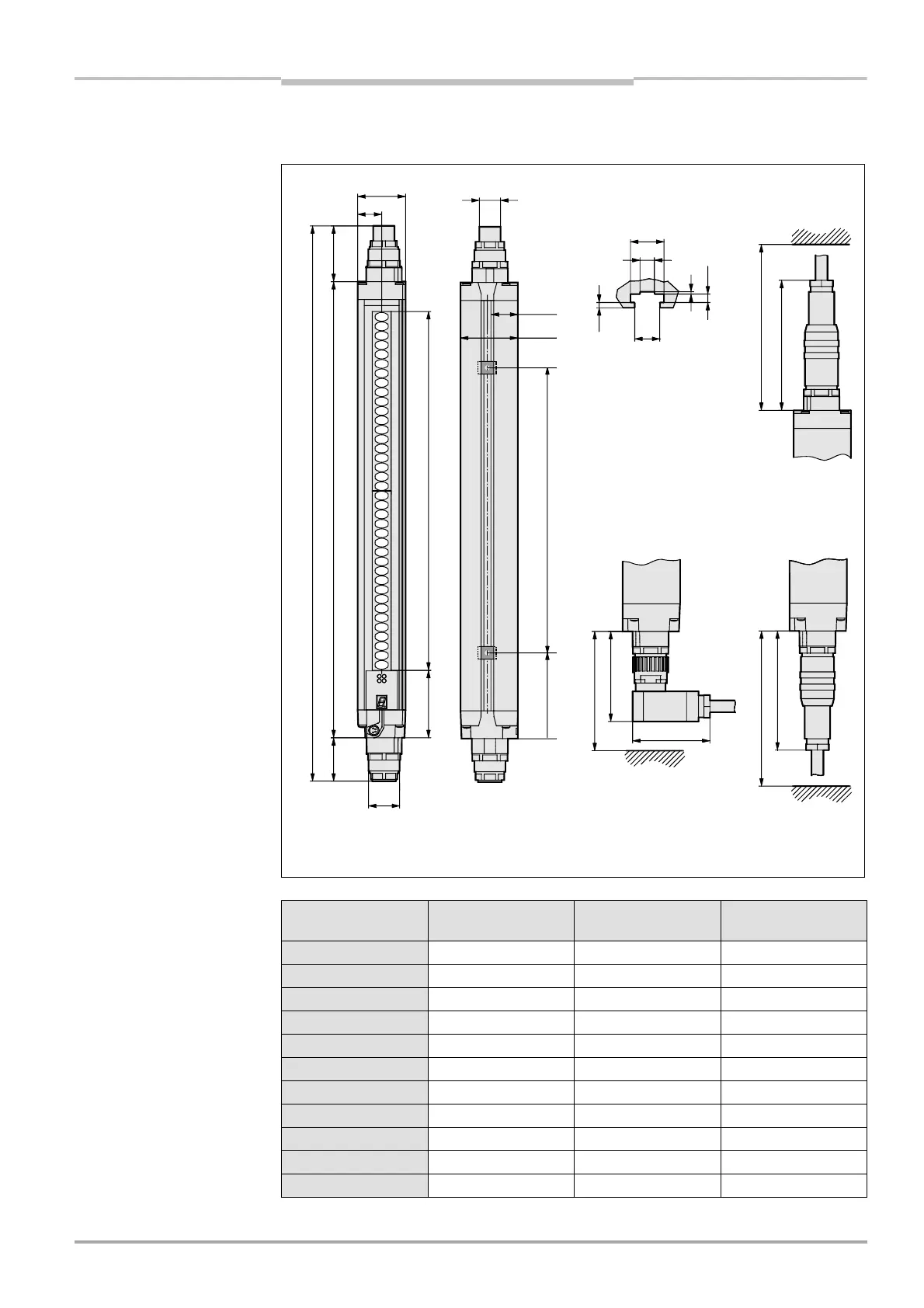
Fig. 30: Dimensional drawing
C 4000 sender, cascadable
system. Receiver, mirror
image (mm)
Protective
field height S [mm]
Dimensions L1
[mm]
Dimensions L2
[mm]
Dimensions A
[mm]
300
381 464 224
450
532 614 374
600
682 765 524
750
833 915 674
900
984 1066 824
1050
1134 1216 974
1200
1283 1366 1124
1350
1435 1517 1274
1500
1586 1669 1424
1650
1736 1818 1574
1800
1887 1969 1724
DIN 43651 plug (M26×11 + FE)
40
48
20
14
46.5
L2
L136.2
56.3 S
22.4
6
10.5
2.2
1
3.5
Sliding nut groove for
side mounting
DIN 43651 socket (M26´11 + FE)
110
approx. 140 (con. range)
100
Cable plug
M26×11 + FE
with crimp
contacts
approx. 150 (conn. range)
A74
approx. 100
(connector range)
75
65
Cable sockets M26×11 + FE
with crimp contacts
Tab. 21: Dimensions depend-
ing on protective field height,
cascadable system

 Loading...
