Operating Instructions Chapter 3
C 4000
20 © SICK AG • Safety Systems • Germany • All rights reserved 8 009 221/16-11-00
Product description
3.5 Indicator elements
The LEDs and the 7-segment display of sender and receiver signal the operating status of
the C 4000.
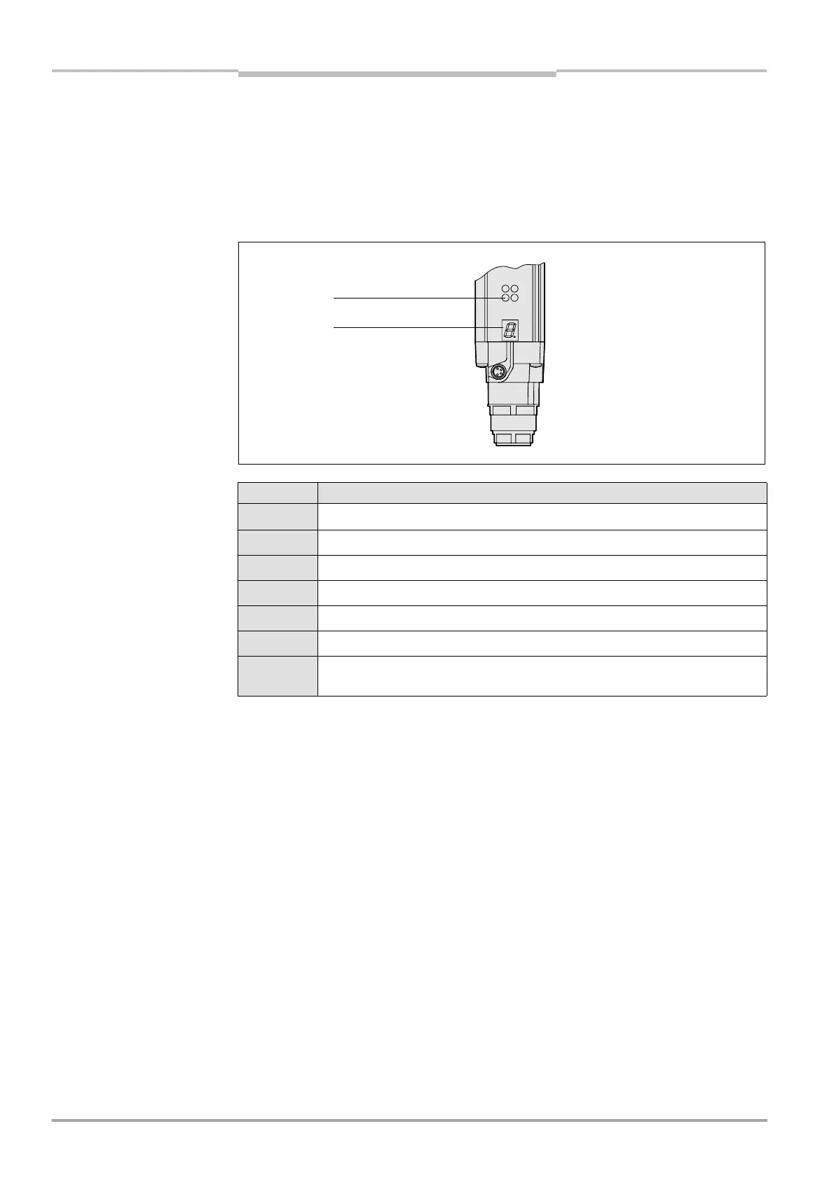
3.5.1 Operation status indicators of the sender
Fig. 13: Indicator elements
of the sender
Display Meaning
[
Yellow: Power supply OK
e
System error. The device is defective. Replace the sender.
o
The device is in the test mode.
u
Non-coded operation (only after switching on)
-
Operation with code 1 (only after switching on)
,
Operation with code 2 (only after switching on)
Other
displays
All other displays are error messages. Please refer to chapter “Fault
diagnosis” on page 40.
Yellow
7-segment display
Tab. 5: Meaning of the
operation indicator elements
of the sender
 Loading...

