Operating Instructions Chapter 5
C 4000
30 © SICK AG • Safety Systems • Germany • All rights reserved 8 009 221/16-11-00
Electrical installation
5 Electrical installation
WARNING
Switch the entire machine system off line!
The machine system could inadvertently start up while you are connecting the unit.
> Make sure that the entire machine/system is disconnected during the electrical instal-
lation.
Notes
· The safety light curtain is a Class A device. It may cause radio interference in residential
areas. If radio interference occurs, the person(s) affected may demand that the operator
take appropriate action for suppressing interference.
· To ensure full electromagnetic compatibility (EMC), functional earthing (FE) must be con-
nected.
· The external voltage supply of the device must be capable of buffering brief mains fail-
ures of 20 ms as specified in EN 60204. Suitable power supplies are available as acces-
sories from SICK (Siemens type series 6 EP 1).
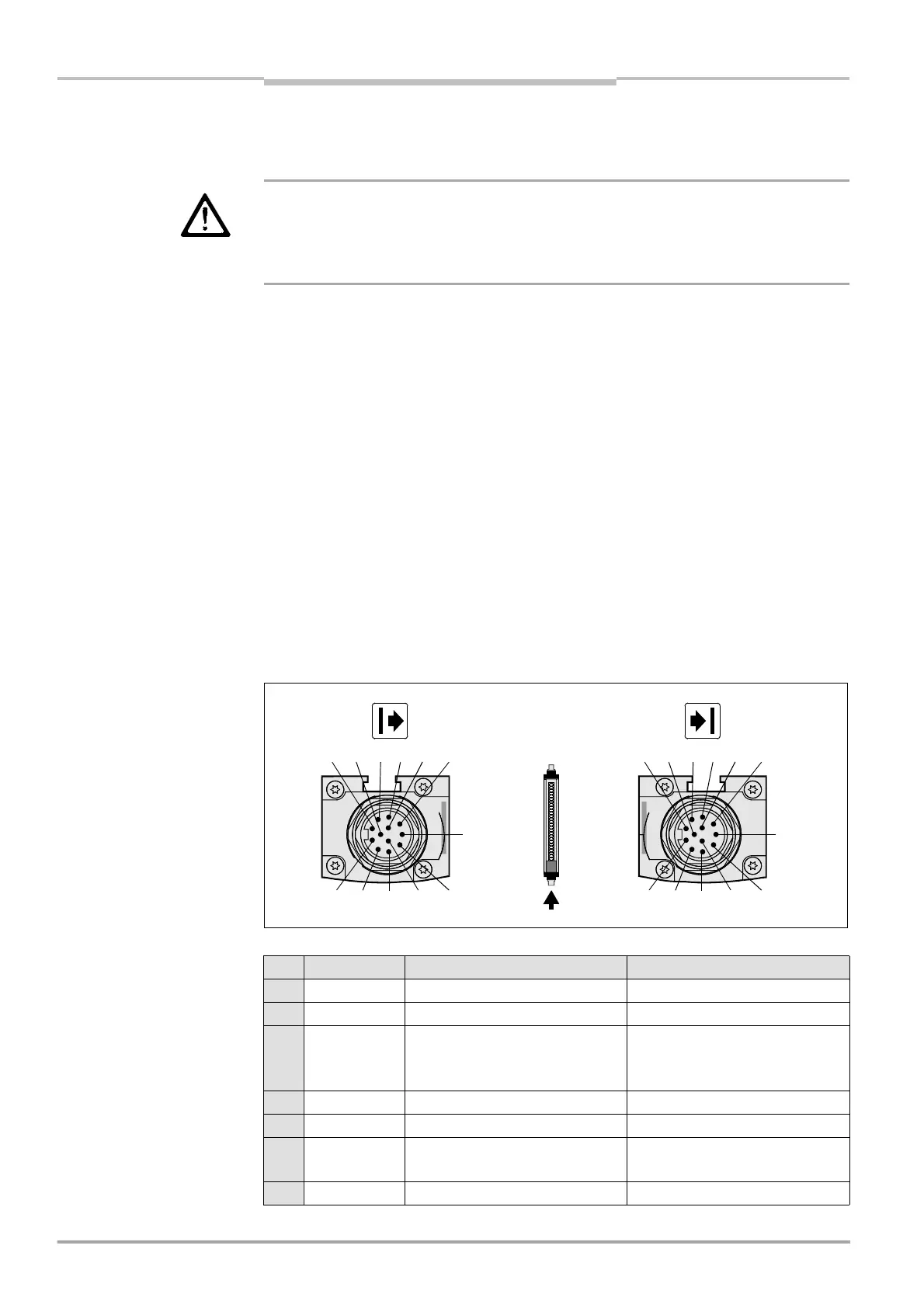
· The plug alignment (direction of turn) in the housing may vary from unit to unit. You can
identify the proper pin assignment by the position of the pins in relation to each other as
shown in the drawings.
· System connections and extension connections in a cascaded system must be connect-
ed only if the system is off line. The RS 232 interface may be connected/disconnected
with the system on line.
5.1 System connection M26×11 + FE
Fig. 23: Pin assignment sys-
tem connection M26×11 + FE
Pin Wire colour I Sender H Receiver
1 brown 24 V DC input (voltage supply) 24 V DC input (voltage supply)
2 blue 0 V DC (voltage supply) 0 V DC (voltage supply)
3grey test input:
0 V: external test active
24 V: external test inactive
OSSD1 (switching output 1)
4 pink reserved OSSD2 (switching output 2)
5 red reserved reset/restart
6 yellow reserved external device monitoring
(EDM)
7 white reserved reserved
4 3 2 9 1
5 10 6 7 11 8
FE
4 3 2 9 1
5 10 6 7 11 8
FE
Tab. 7: Pin assignment system
connection M26×11 + FE

 Loading...
