Operating Instructions Chapter 5
C4000
Electrical installation
8 009 221/16-11-00 © SICK AG • Safety Systems • Germany • All rights reserved 31
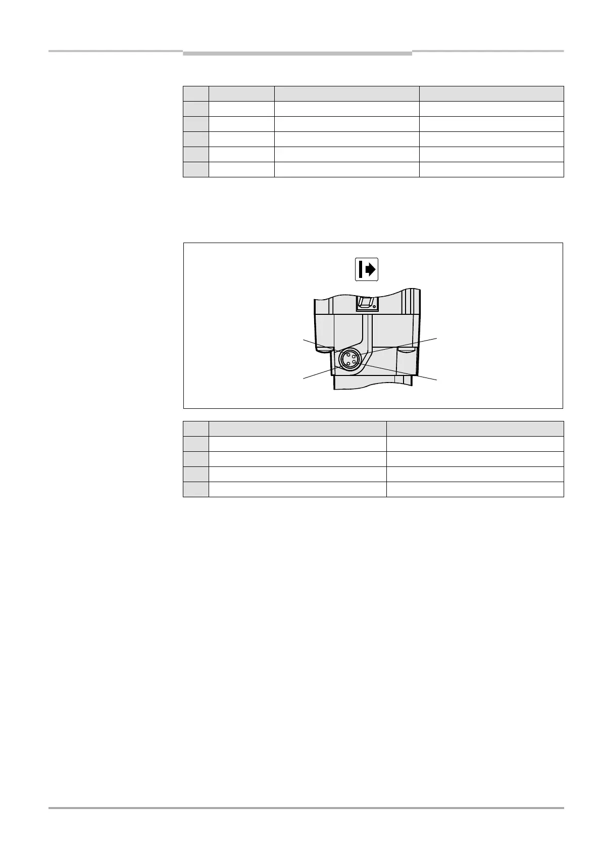
5.2 Configuration connection
M8×4 (serial interface)
Fig. 24: Pin assignment config-
uration connection M8×4
Notes The pin assignment of sender and receiver is identical.
> After the configuration of the device has been completed, press the attached protection
cap over the configuration connection.
8 red/blue reserved reserved
9 black device communication device communication
10 purple device communication device communication
11 grey/pink input host/guest SEL input host/guest SEL
FE green functional earthing functional earthing
Pin Wire colour I Sender H Receiver
Tab. 7: Pin assignment system
connection M26×11 + FE
(contd.)
Pin I Sender/H receiver PC-side RS 232 SubD
1 not assigned
2RxD pin 3
3 0 V DC (voltage supply) pin 5
4TxD pin 2
3
1
4
2
a
.
:
n ass
gnment
configuration connection
M8×4

 Loading...
