Operating Instructions Chapter 5
C 4000
32 © SICK AG • Safety Systems • Germany • All rights reserved 8 009 221/16-11-00
Electrical installation
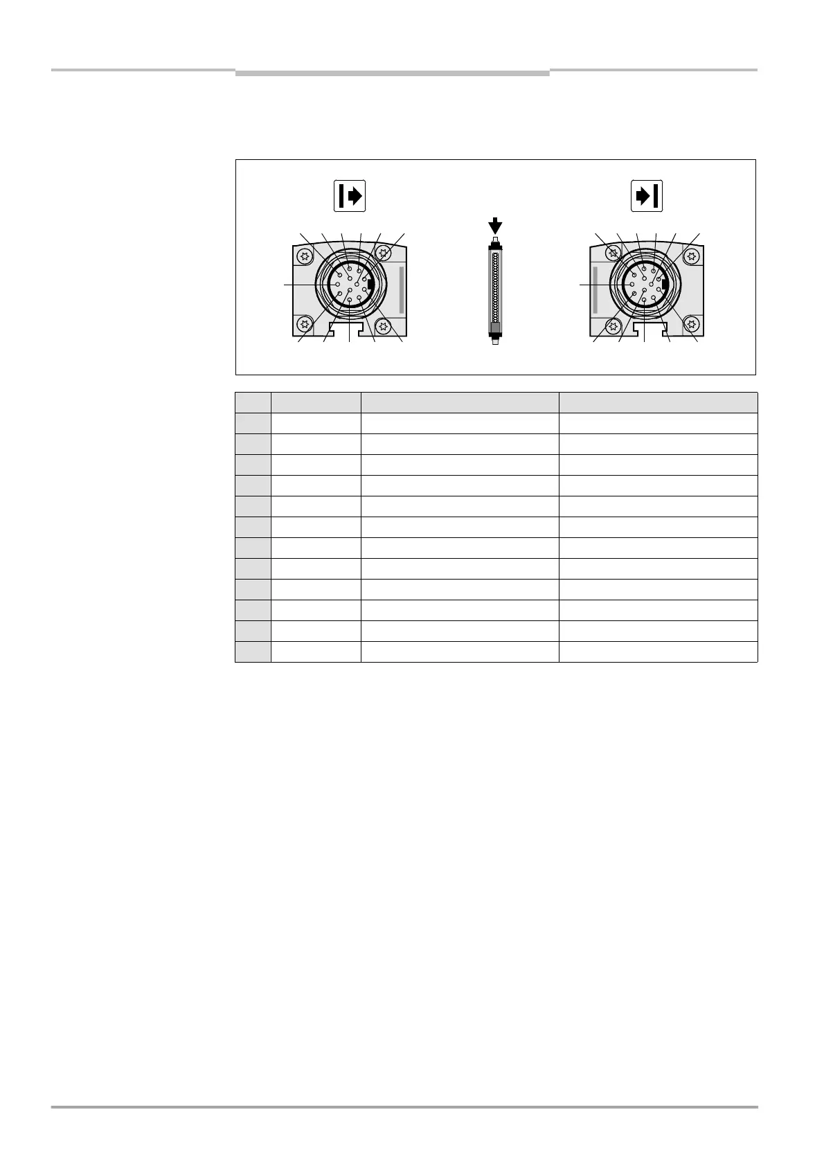
5.3 Extension connection M26×11 + FE
Fig. 25: Pin assignment exten-
sion connection M26×11 + FE
Note > If the extension connection is no longer needed, always screw the attached protective
cap over the extension connection.
Pin Wire colour I Sender H Receiver
1 brown 24 V DC output (voltage supply) 24 V DC output (voltage supply)
2 blue 0 V DC (voltage supply) 0 V DC (voltage supply)
3 grey reserved reserved
4 pink reserved reserved
5 red reserved reserved
6 yellow reserved reserved
7 white reserved reserved
8 red/blue reserved reserved
9 black device communication device communication
10 purple device communication device communication
11 grey/pink output host/guest SEL output host/guest SEL
FE green functional earthing functional earthing
1 9 2 3 4
8 11 7 6 10 5
FE
1 9 2 3 4
8 11 7 6 10 5
FE
a
.
:
n ass
gnment
extension connection
M26×11 + FE

 Loading...
