Operating Instructions Chapter 9
C4000
Fault diagnosis
8 009 221/16-11-00 © SICK AG • Safety Systems • Germany • All rights reserved 41
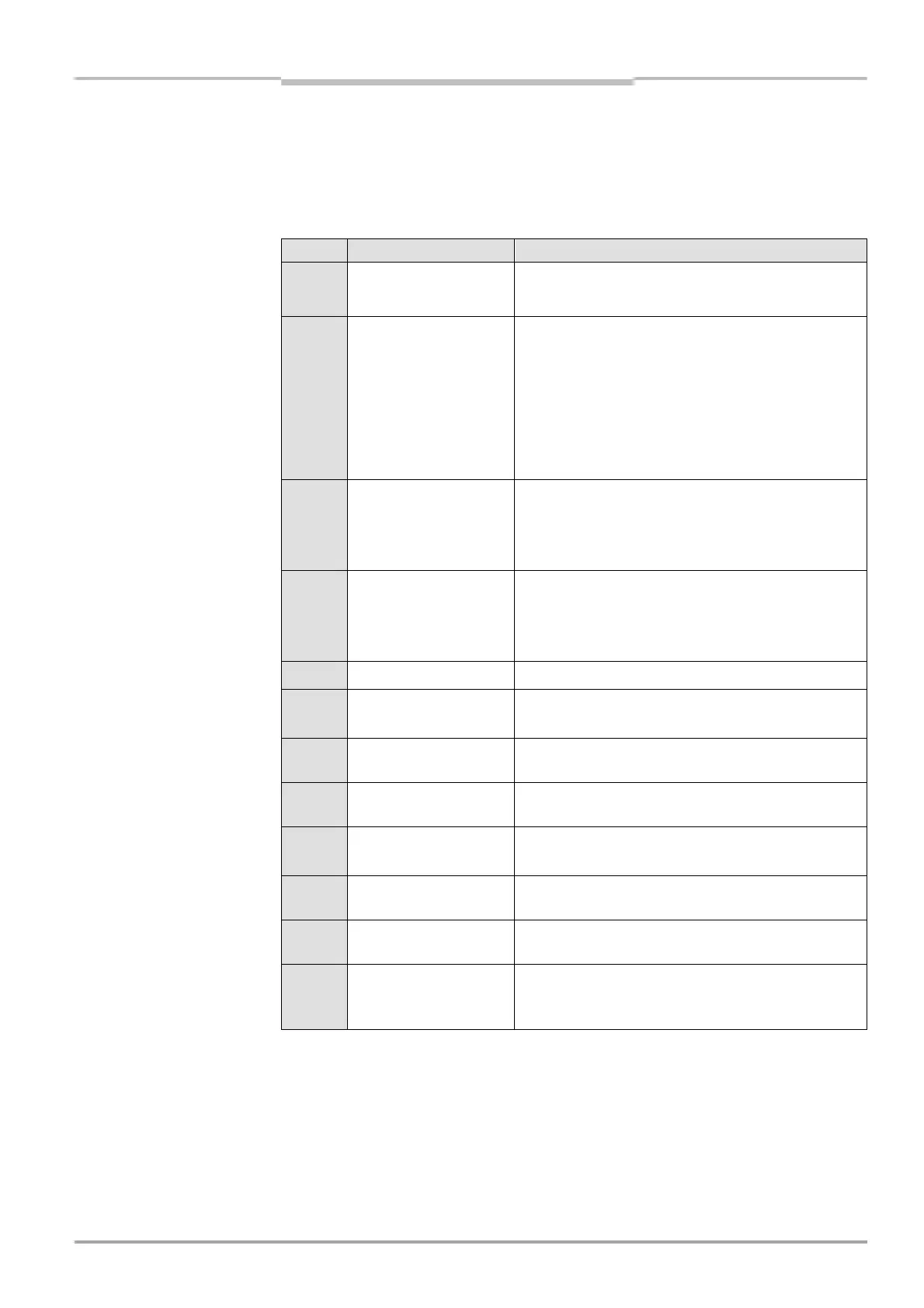
9.4 Error displays of the 7-segment display
This chapter explains the meaning of the error displays of the 7-segment display and how
to respond to the messages. Please refer to chapter “Indicator elements” on page 20 for a
description of the 7-segment display.
Display Cause Remedying the error
0,1
or
2
Inadequate alignment > Re-align sender and receiver (see page 35).
The display goes off after 2 minutes.
6
Configuration
incomplete
> The display goes off automatically once the con-
figuration has been successfully transferred.
If display 6 does not go off:
> Check the configuration of the system using the
CDS (Configuration & Diagnostic Software).
> Re-transfer the corrected configuration to the
system.
8
or
(
EDM error > Check the contactors and their wiring, eliminate
any wiring errors, if necessary.
> If ( is displayed, switch the device off and back
on again.
9
Error in reset button/
restart button
> Check the reset button/restart button for proper
function. The button may be defective or stuck.
> Check the wiring of the reset button/restart but-
ton for any short circuit at 24 V.
e
System error > Replace the unit (receiver or sender).
f@1
Overcurrent at
switching output 1
> Check the contactor. Replace, if necessary.
> Check the wiring for short-circuit at 0 V.
f@2
Short circuit at
switching output 1
> Check the wiring for short-circuit at 24 V.
f@3
Short circuit at
switching output 1
> Check the wiring for short-circuit at 0 V.
f@4
Overcurrent at switch-
ing output 2
> Check the contactor. Replace, if necessary.
> Check the wiring for short-circuit at 0 V.
f@5
Short circuit at switch-
ing output 2
> Check the wiring for short-circuit at 24 V.
f@6
Short circuit at
switching output 2
> Check the wiring for short-circuit at 0 V.
f@7
Short circuit between
switching output 1
and 2
> Check the wiring and remedy the error.
Tab. 14: Error displays of
the 7-segment display

 Loading...
