Operating Instructions Chapter 10
C 4000
44 © SICK AG • Safety Systems • Germany • All rights reserved 8 009 221/16-11-00
Technical specifications
Permissible line resistance
between device and load
8)
2.5 W
Supply lead 1 W
ON time after light beam
disruption
double
response time
Power consumption 3 A (host/
guest/guest)
Contactors
Permissible fall time 300 ms
Permissible response time 300 ms
Control switch input
9)
15 V 24 V 28.8 V
Weight Depending on protective field height (see page 47)
Operating data
Connection Hirschmann plug M26×11 + FE
Cable length Depending on load, power supply and wire cross-
section. The technical specifications must be
observed.
Wire cross-section
10)
0.75 mm
2
Ambient operating temperature 0°C +55°C
Air humidity (non-dewing) 15% 95%
Storage temperature –25°C +70°C
Housing cross-section 40 mm × 48 mm
Rigidity 5 g, 10-55 Hz acc. to IEC 68-2-6
Shock resistance 10 g, 16 ms acc. to IEC 68-2-29
1)
The external voltage supply must be capable of buffering brief mains failures of 20 ms as specified in
EN 60204. Suitable power supplies are available as accessories from SICK (Siemens type series 6 EP 1).
2)
Within the limits of U
V
.
3)
Applies to the voltage range between U
V
and 0 V.
4)
In compliance with IEC 61131.
5)
In case of malfunction (disruption of 0 V lead) the output acts like a resistor >13 kW after U
V
. The down-
stream controller must detect this status as LOW. A safe SPC (Stored-Programme Controller) must be able
to identify this status.
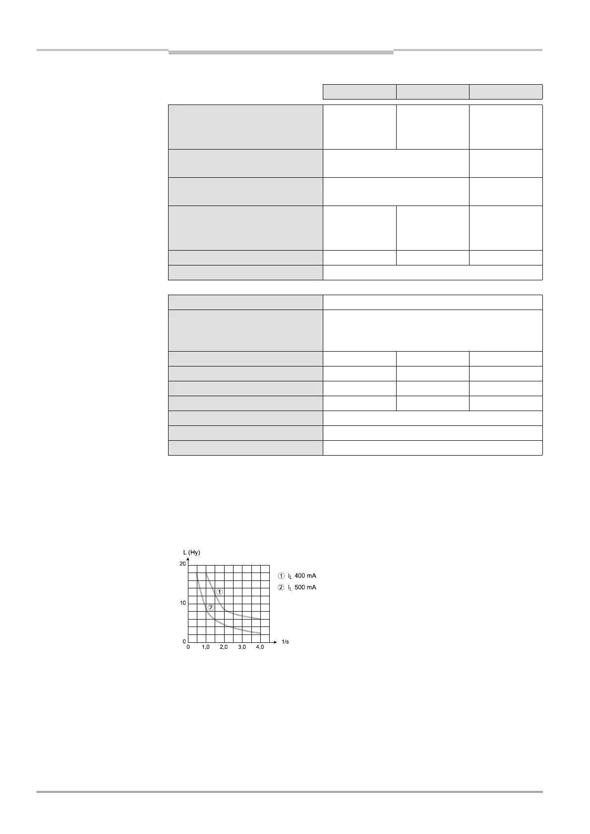
6)
The maximum rated load inductance is higher with lower switching sequence.
7)
When active, the outputs are tested cyclically (brief LOW). When selecting the downstream controllers,
make sure that the test pulses do not result in deactivation when using the above parameters.
8)
Make sure to limit the individual line core resistance to the downstream controller to this value to ensure
that the cross-circuit between the outputs is safely detected. (Also note EN 60204 Electrical Machine
Equipment, Part 1: General Requirements.)
9)
In compliance with IEC 61131-2.
10)
Maximum cable length £ 50 m.
minimum typical maximum
Tab. 15: Technical specifi-
cations C 4000 (contd.)

 Loading...
