OPERATING INSTRUCTIONS | CFP CUBIC 8021989 / 2017-10-20 | SICK AG
Subject to change without notice
16
6 ELECTRICAL INSTALLATION
6.2 Electrical connection
6.2.1 Overview of the electrical connections
The sensor is connected using a pre-assembled female cable connector with 1 x M12
plug connector (5-pin or 8-pin). With the power switched off, plug the female cable con-
nector into the sensor and screw it tight.
Connect the cable according to its function. After the supply voltage has been applied,
the sensor carries out a self-test. Once installed, the sensor is ready for operation on
completion of the self-test (< 5 s) and the display shows the current measured value.
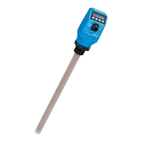
Fig. 3: CFP Cubic device view
6.2.2 Pin assignment, M12 plug connector, 5-pin (depending on the variant)
Fig. 4: M12 x 1 plug connector, 5-pin
Pin Identication Description
1 L+ Supply voltage
2 Q
A
Current output 4 ... 20 mA
Or
Voltage output 0 ... 10 V
Variant-dependent
3 M Ground, reference potential for
current/voltage output
4 C/Q
1
Switching output 1, PNP / NPN / DRV (push-pull) / IO-Link
5 Q
2
Switching output 2, PNP / NPN / DRV (push-pull)