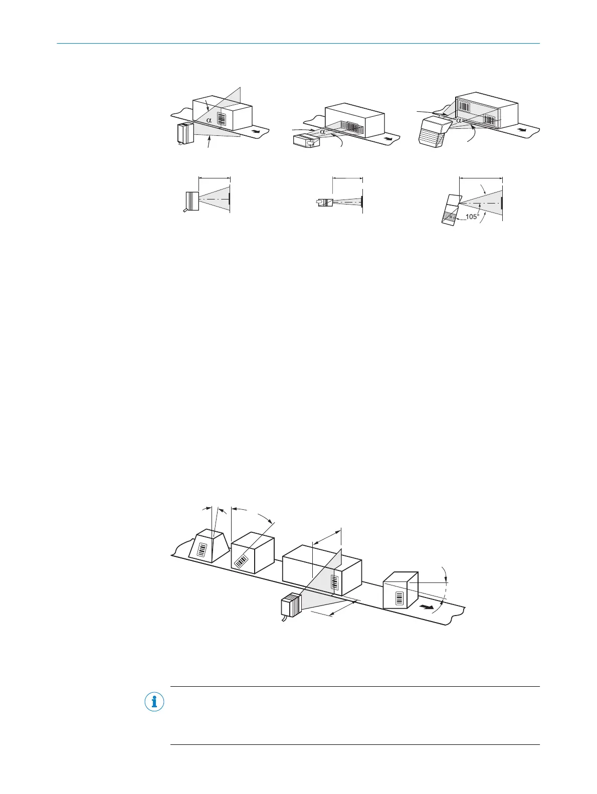
Grid scanner
Line scanner
Reading distance a Reading distance a
Reading distance a
Central system 105° = default
Line scanner with oscillating mirror
Figure 16: Line scanner, grid scanner and line scanner with oscillating mirror
5.4.2 Reading distance to the bar code and aperture angle α
The maximum distance from the reading window of the device to the bar code may not
exceed the design values for the device. Because of the V-shaped deflection of the
beams, the usable length of the scan line for evaluation (reading field height) depends
on the reading distance.
In the specification diagrams, the height of the reading field dependent on the reading
distance is shown for differing resolutions (module widths), see "Reading field condi‐
tions", page 64.
5.4.3 Angle alignment of the device
The optimum alignment of the device is achieved when the scan line crosses the
stripes of the bar code as close to a right angle as possible (tilt and pitch). Possible
reading angles that can arise between scan line and bar code at all three levels in the
area must be taken into account.
In order to avoid surface reflections, the rotation angle should be around 105°, see
"Avoidance of surface reflections", page 28.
Figure 17: Line scanner: Read angle occurring between scanning line and bar code
1
Depth of field
2
Reading distance
NOTE
The specified maximum values can only be reached in optimum conditions. The actual
maximum depends on module width, code type, print contrast, ambient light, distance
and scanning frequency.
MOUNTING 5
8019588/2017-01-20 | SICK O P E R A T I N G I N S T R U C T I O N S | CLV63x, CLV64x, CLV65x
27
Subject to change without notice