Angle Limit Value
Tilt α CLV63x, CLV64x: max. 30°
CLV65x: max. 45°
Pitch β Max. 45°
Skew γ Max. 45°
Table 4: Permitted read angle between scanning line and bar code
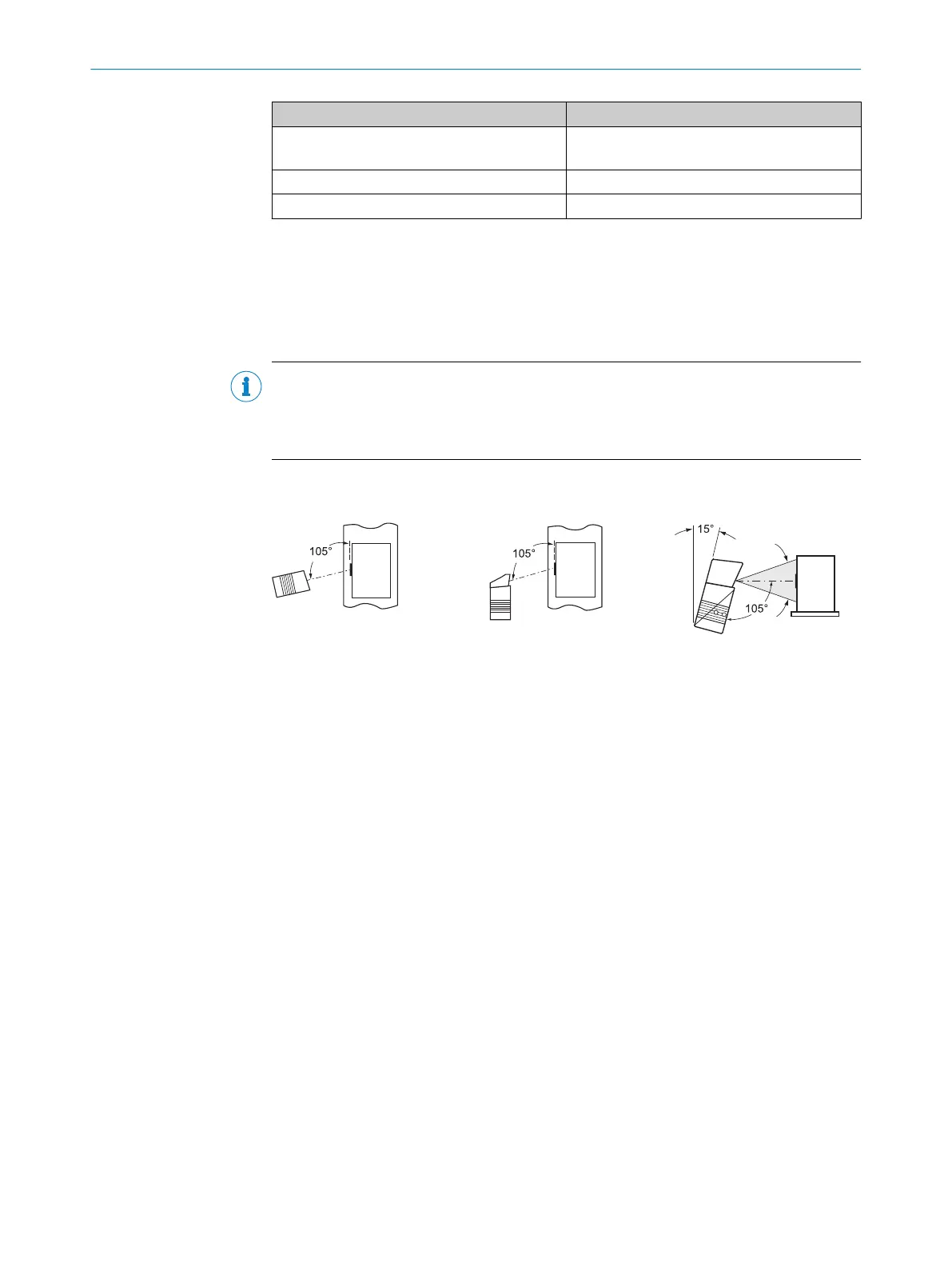
5.4.4 Avoidance of surface reflections
If the light of the scan line(s) hits the surface of the bar code precisely vertically, this
may cause interference when the light reflected back is received. To prevent this effect,
the device must be mounted so that the light emitted is tilted relative to the vertical.
NOTE
Optimum results are achieved when the scan line tilts approx. 15° from the vertical.
In devices with an oscillating mirror, these values relate to the central position of the
scan field.
Line scanner
(reading window on side)
Line scanner
(reading window on front)
Line scanner with oscillating mirror
(reading window on side)
(top view)
(side view)
Central position 105° = default
(top view)
Figure 18: Avoiding surface reflections on the example line scanner – angle between light emit‐
ted and bar code (tilting away from vertical)
5.4.5 Count direction of the reading angle and the code angle
The device can scan and decode several bar codes at each reading.
At the same time, the location-specific reading diagnostics data are determined for
each of them.
■
The reading angle, starting from the reading window, at which the device detects
the bar code center on the red scanning line of the deflected scanning beam, can
be output as an RA (reading angle) value.
■
In addition, in the device with oscillating mirror, the angle of deflection of the scan
line under which the device detects the bar code on the red scan line can be
released as the CA (code angle) value.
By determining the RA/CA value, identical bar codes (code type, code length, and data
content) can be separated, and the bar code data can be assigned due to its position
on the object.
5 MOUNTING
28
O P E R A T I N G I N S T R U C T I O N S | CLV63x, CLV64x, CLV65x 8019588/2017-01-20 | SICK
Subject to change without notice