Additional information on this can be found in the operating instructions for the rele‐
vant module.
6.6.3 Wiring the CAN interface
If the wiring of the CAN interface is carried out via a connection module, then the rele‐
vant operating instructions of the module used must be followed.
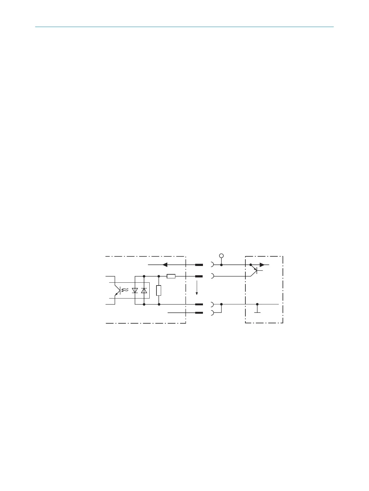
6.6.4 Wiring digital switching inputs
Physical switching inputs on the device
The physical switching inputs can be used for starting and/or ending the reading pulse
or for feeding an incremental signal.
Depending on the device, there are different number of switching inputs available on
the connections, see "Pin allocation of the connections", page 36.
The switching inputs are each designed to be opto-decoupled and reverse polarity pro‐
tected.
Switching behavior: power at the input starts the internal reading interval of the device
(default: active high, debounce: max. 30 ms (standard)).
Electrical values
The electrical values calculated are identical for all switching inputs.
Low: |U
e
| ≤ 2 V; |I
e
| ≤ 0.3 mA
High: 6 V ≤ |U
e
| ≤ 32 V; 0.7 mA ≤ |I
e
| ≤ 5 mA
PNP sensorSwitching input
Signal
3.32K
6.64K
1
2
3
4
Sensor GND
U
V
U
V
U
V
U
e
GND
GND
Figure 35: Wiring of a switching input via external PNP sensor
1
Supply voltage U
s
2
Signal line (e.g. “Sensor 1”)
3
SensGND
4
GND
ELECTRICAL INSTALLATION 6
8019588/2017-01-20 | SICK O P E R A T I N G I N S T R U C T I O N S | CLV63x, CLV64x, CLV65x
45
Subject to change without notice