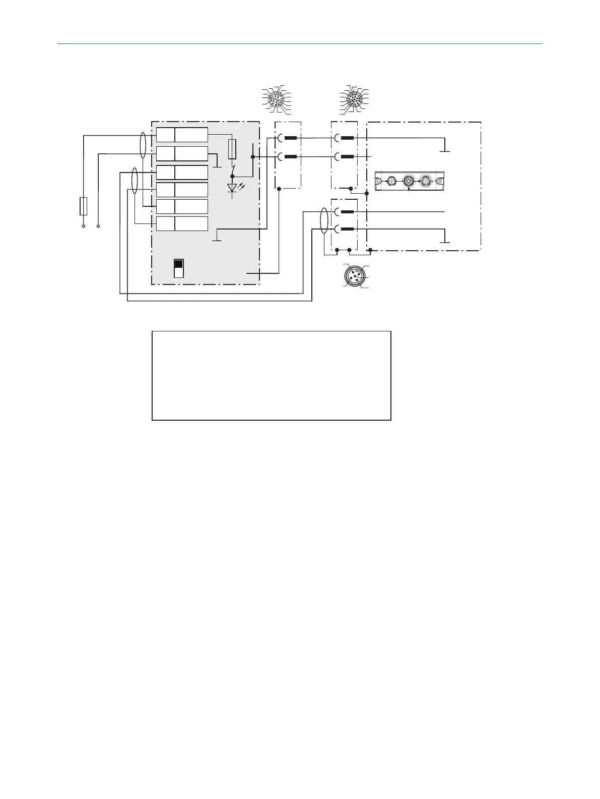
Wire supply voltage for CLV69x-xxx1 in the CDB650-204 connection module
CLV69x-xxx1 (with heating)
CDB650-204
U
V
U
V
2
1
2
2)
3
6
Shield
5
Shield
1 U
IN
2 GND
2 U
IN
2 GND
S1
F
M12 male connector, 5-pin,
A-coded
Cable
1)
, e.g. no. 6053224 (5m)
GND
GND
ON
OFF
S1: POWER
DC 21.6V
... 28.8V
Max.
4A
U
IN
*
POWER
1) Adapter cable:
No. 6053224 (5m)
No. 6053225 (10m)
Cloning plug
No. 2062452 (B)
Connection
“CAN 1”
4
2
3
5
1
Red
Gray
Blue
17
16
10
11
12
15
14
6
5
4
13
7
8
9
1
2
3
GND
Shield
1
2
17
16
10
11
12
15
14
6
5
4
13
7
8
9
1
2
3
M12,
17-pin,
A-coded
F
Switch S1:
ON:
Supply voltage U
IN
connected via fuse as U
IN
* to CDB650-204
and CLV69x.
Voltage U
IN
* can also be tapped at terminal 11 and 14.
OFF:
CDB650-204 and CLV69x separated from supply voltage.
Recommended setting for all connection work.
2) Pin 2 in the
CLV69x-xxx1
(with heating)
not connected
.
.
.
.
.
.