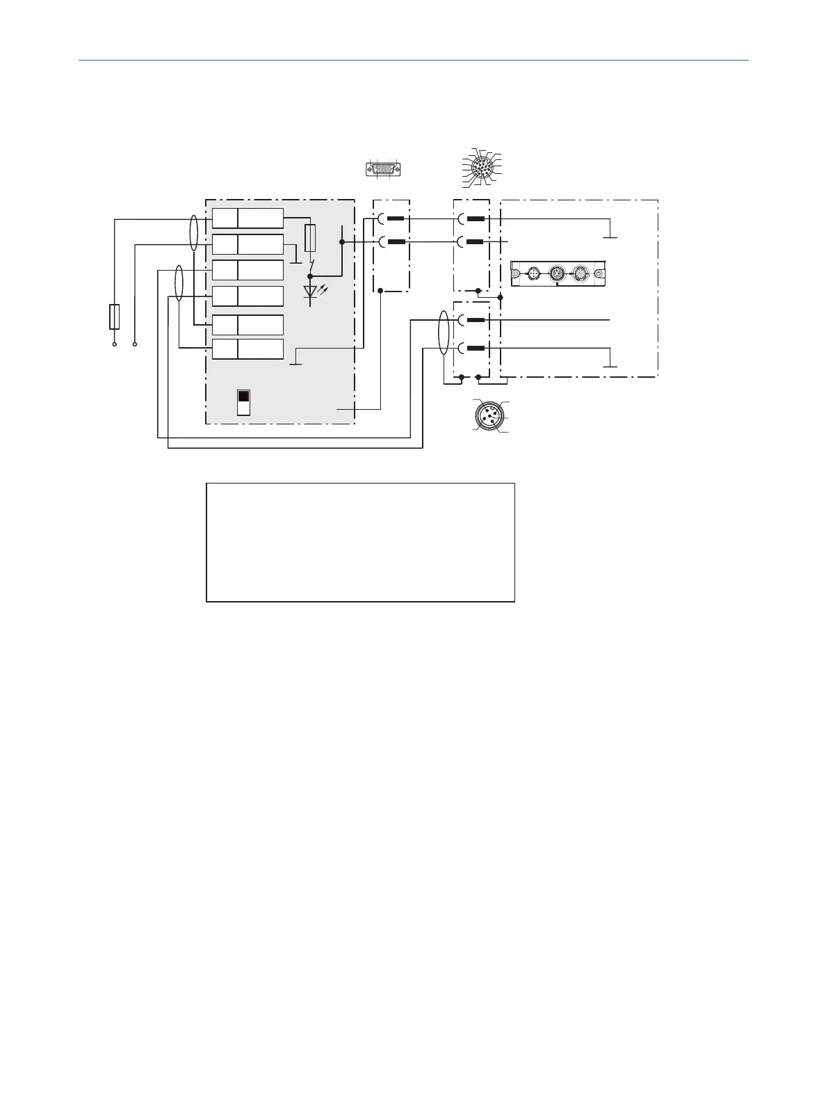
Wire supply voltage for CLV69x-xxx1 in the CDM420-0006 connection module
CLV69x-xxx1 (with heating)
CDM420-0006
1
2
3
5
5
Shield
6
Shield
1 +24V
2 GND
3 +24V
4 GND
GND
S1
F
U
V
U
V
Shield
D-Sub-HD
female connector,
15-pin
M12 male connector,
17-pin, A-coded
GND
GND
.
.
.
ON
OFF
S1 : POWER
+24V*
POWER
17
16
10
11
12
15
14
6
5
4
13
7
8
9
1
2
3
6110 5
1115
Cloning plug
No. 2062452
Max.
4A
F
M12 male connector 5-pin,
A-coded
1) Adapter cable:
No. 6053224 (5m)
No. 6053225 (10m)
Connection
“CAN 1”
4
2
3
5
1
Switch S1:
ON:
supply voltage U
V
(+24V) switched via fuse as U
V
(+24V*)
to CDM420-0006 and CLV69x.
U
V
(+24V*) can also be engaged at terminal 29 and 39.
OFF:
CDM420-0006 and CLV69x separated from supply voltage.
Recommended position for all connection types.
Adapter cable
1)
DC 21.6V
... 28.8V
red
Gray
Blue
2) Pin 2 in CLV69x-xxx1
(with heating) not
connected
2
2)
1