6
1
10
5
11
15
6
1
10
5
11
15
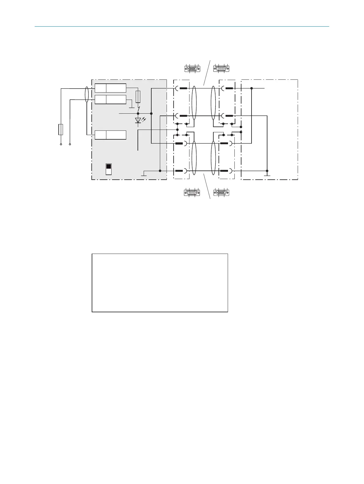
Wire supply voltage for CLV69x-xxx0 in the CDM490-0001 connection module
CDM490-0001
(basic card)
U
V
U
V
U
V
= DC 18 ... 30V
1
5
1
5
5
Shield
1 +24V
2 GND
+24V*
GND
S1
F
Shield
D-Sub-HD
D-Sub-HD
Cable 1, e.g. no. 2020302 (3m)
Cable 2, e.g. no. 2020302 (3m)
GND
.
.
.
.
.
.
.
.
.
1
5
1
5
.
.
.
.
.
.
.
.
.
ON
OFF
S1 : POWER
+24V*
POWER
+) If no switching inputs and outputs of the CLV69x are used, cable 2 does not have to be used
10 5 61
15 11
10 5 61
15 11
1
2
1 “HOST/AUX/I/O” connection
2 “I/O” connection
CLV69x-xxx0
(without heating)
DC 18V ... 30V
Max.
2A
F
U
V
= DC 18V ... 30V at terminal +24V =
U
V
at terminal +24V* after switch S1, protected by internal fuse F
Switch S1:
ON:
supply voltage U
V
(+24V) switched via fuse as U
V
(+24V*)
to CDM490-0001 and CLV69x.
U
V
(+24V*) can also be engaged on terminal 29 of the basic
card as well as on terminal 51 ... 53 of the I/O card.
OFF:
CDM490-0001 and CLV69x separated from supply voltage.
Recommended position for all connection types.