2 auxiliary (Q3, Q4, In2)
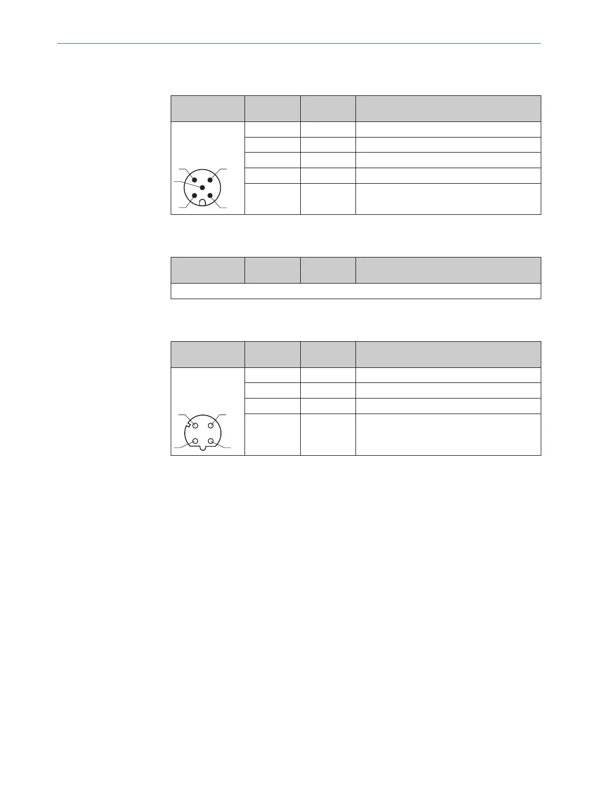
Table 26: Pin assignment connection 2: Auxiliary
Male/female
connector
Contact Short form Signal description
M12 male con‐
nector, 5-pin A-
coded
1 nc
2 Q3 Push-pull digital output
3 nc
4 Q4 Push-pull digital output
5 In2 Digital input (internal pull-down)
3 NC
Table 27: Pin assignment connection 3: NC
Male/female
connector
Contact Short form Signal description
Not used
4 Ethernet
Table 28: Pin assignment connection 4: Ethernet
Male/female
connector
Contact Short form Signal description
M12 female con‐
nector, 4-pin D-
coded
1 TX+ Transmit data positive
2 RX+ Receive data positive
3 TX- Transmit data negative
4 RX- Receive data negative
6 ELECTRICAL INSTALLATION
46
O P E R A T I N G I N S T R U C T I O N S | DT1000 and DL1000 8019329/12TZ/2019-03-28 | SICK
Subject to change without notice