Switching
function
Switching state Voltage at Q
i
at active state = High Voltage at Q
i
at active state = Low
Distance
window
Inactive
Active
SP1
Hysteresis
Output value
distance
Switching
state
SP2
Hysteresis
SP1
Hysteresis
Output value
distance
SP2
Hysteresis
Voltage
High
Low
SP1
Hysteresis
Output value
distance
SP2
Hysteresis
Voltage
High
Low
Object
speed
Inactive
Active
Absolute value of
output value speed
Switching
state
SP
Hysteresis
Absolute value of
output value speed
SP
Voltage
High
Low
Hysteresis
Absolute value of
output value speed
SP
Voltage
High
Low
Hysteresis
3.6 Measured value technology
After application of the supply voltage and initialization, the device is ready for mea‐
surement.
The quality of the measured values in relation to noise and reliability can be optimized
in line with the given application. The following parameters are available here.
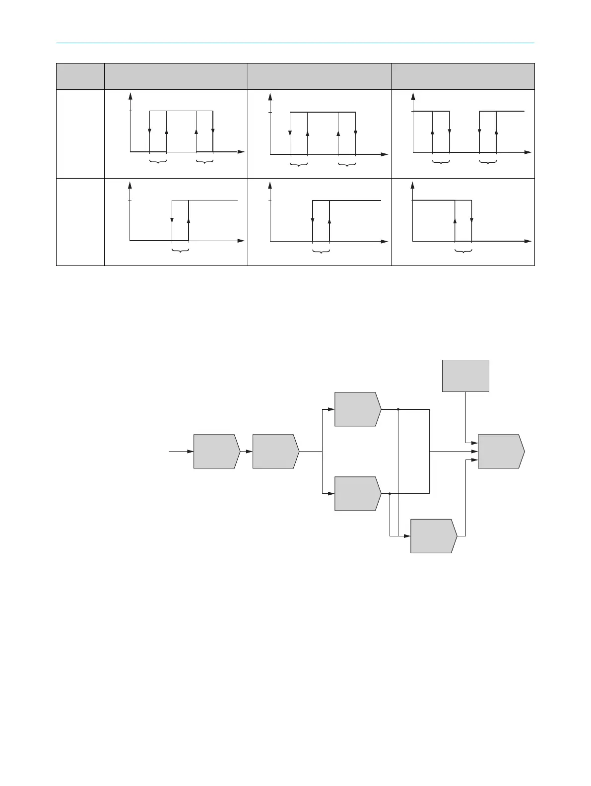
Echo
c Measurement
cycle time
Measurement
core
Echo selection
Substitute values
upon "No echo"
and errors
Output
calculation
c Distance range
c Signal level range
c First / Last Echo
c Rain and snow filter
c Fog filter
c Measurement
direction
c Offset / Preset value
Distance:
Mowing
average filter
Distance:
Kalman filter
c Filter depth
c On / Off
c Filter depth
Object speed:
Mowing
average filter
Figure 4: Measured value technology
Measurement cycle time
Increasing the measurement cycle time causes a rise in sensor detectability. A mea‐
sured value can thus be created from very low signal strengths.
In product variant DT1000, the scalability of the range results from this: the longer the
set measurement cycle time, the larger the range of the sensor, see figure 30,
page 98.
For more information on the measurement cycle time, see "Defining the measurement
cycle time", page 54.
PRODUCT DESCRIPTION 3
8019329/12TZ/2019-03-28 | SICK O P E R A T I N G I N S T R U C T I O N S | DT1000 and DL1000
17
Subject to change without notice

 Loading...


