•
During installation, comply with the special requirements created by the environ‐
ment (applications from good professional practice concerning cable error: best
possible separation of cables susceptible to interference (e.g., devices, bus
cables) from faulty cables (e.g., motor control, brakes).
•
The transmission rate via the SSI interface depends on the length of the cable:
Table 24: SSI interface: Maximum transmission rate depending on the length of cable
Cable length [m] Transmission rate [kHz]
< 25 m 500 kHz
< 50 400
< 100 300
< 200 200
< 400 100
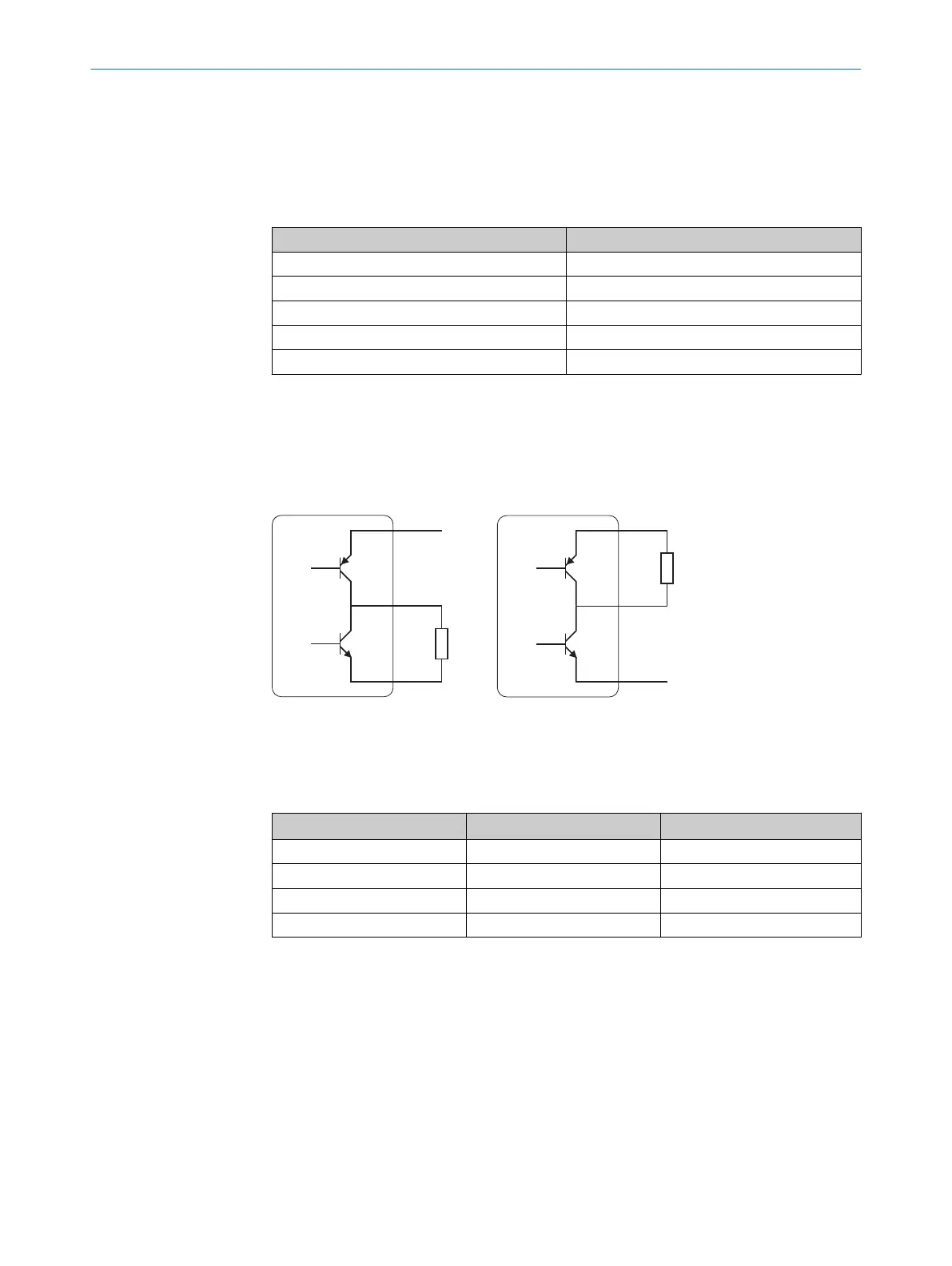
6.2.1 Digital outputs
The digital outputs are designed as push-pull outputs. That means that the signal on Q
i
is connected either to L
+
(for PNP controls) or M (for NPN controls) depending on the
active state.
Figure 17: Digital output simplified diagram
The “Active status” function (can be configured using the device menu) specifies what
electric voltage level is applied to the digital output based on the switching state of the
respective digital output.
Switching state Active status (adjustable) Voltage at Q
i
Active High High
Active Low Low
Inactive High Low
Inactive Low High
ELECTRICAL INSTALLATION 6
8019329/12TZ/2019-03-28 | SICK O P E R A T I N G I N S T R U C T I O N S | DT1000 and DL1000
43
Subject to change without notice
 Loading...


