Pin assignment
I8
I10
I12
X2
X4
I2
I4
I6
I7
I9
I11
X1
X3
7
9
1
1
13
15
8
10
12
14
16
3
5
1 2
4
7
9
11
13
15
17
10
12
14
16
18
5
7
3 4
6
8
1 2
X6
X8
Q
2
Q4
A2
I14
I16
I18
I20
I1
I3
I5
X5
X7
Q
1
Q3
A1
I13
I15
I17
I19
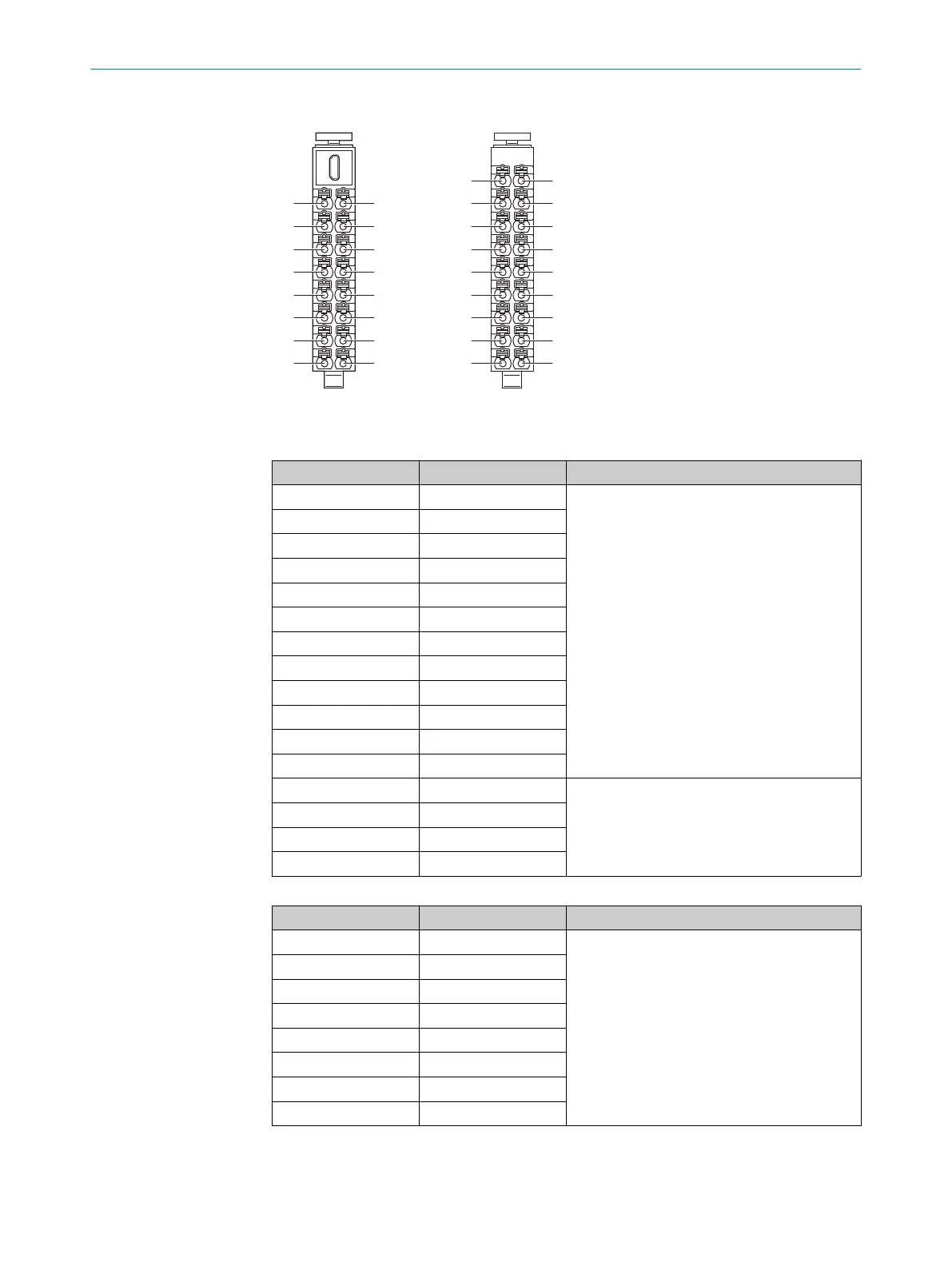
Figure 22: Terminals on front connectors
T
able 6: Left front connector pin assignment
Terminal Pin assignment Description
1 I1 Safety capable input
2 I2
3 I3
4 I4
5 I5
6 I6
7 I7
8 I8
9 I9
10 I10
11 I11
12 I12
13 X1 Test output
14 X2
15 X3
16 X4
Table 7: Right front connector pin assignment
Terminal Pin assignment Description
1 I13 Safety capable input
2 I14
3 I15
4 I16
5 I17
6 I18
7 I19
8 I20
6 ELECTRICAL INSTALLATION
36
O P E R A T I N G I N S T R U C T I O N S | Flexi Compact 8024589/2020-11-10 | SICK
Subject to change without notice