Front connector 6
C C C C C
Front connector 7
C C C C C
… …
•
3-of
-7 coding: 35 front connectors can be uniquely coded.
Coding
1 2 3 4 5 6 7
Front connector 1
C C C C
Front connector 2
C
C C C
… …
Front connector 5
C C C C
Front connector 6
C C C C
… …
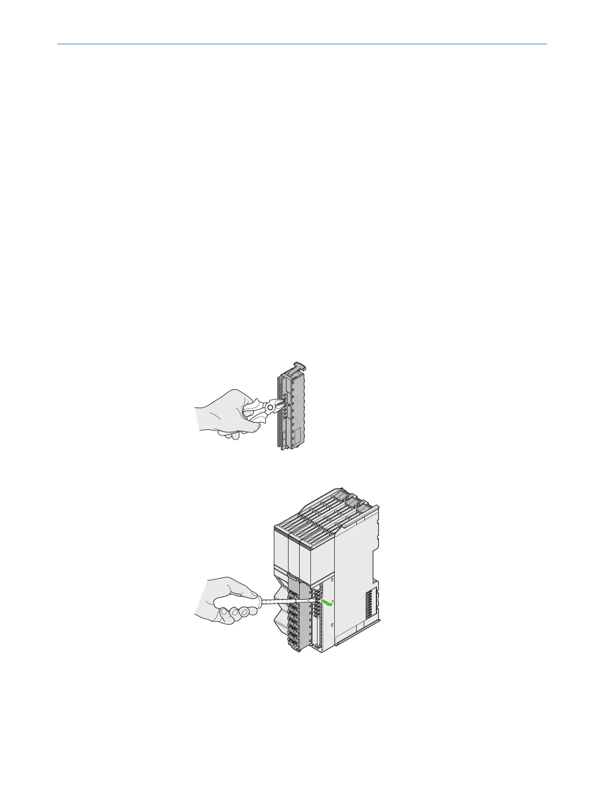
6.3.1 Coding front connector and module
Prerequisites
•
S
lotted screwdriver 3.5 mm × 0.6 mm
•
Diagonal cutter
Approach
Each front connector contains seven coding ribs. The modules have seven coding
elements each for each front connector.
1. Remove the coding ribs on the front connector with wire cutters.
2. Insert the slotted screwdriver vertically on the left next to the respective coding
e
lement.
3. Tip the coding element to the right with a slotted screwdriver.
✓
T
he coding element engages.
Complementary information
You can not reattach a removed coding rib to the front connector.
6 ELE
CTRICAL INSTALLATION
38
O P E R A T I N G I N S T R U C T I O N S | Flexi Compact 8024589/2020-11-10 | SICK
Subject to change without notice