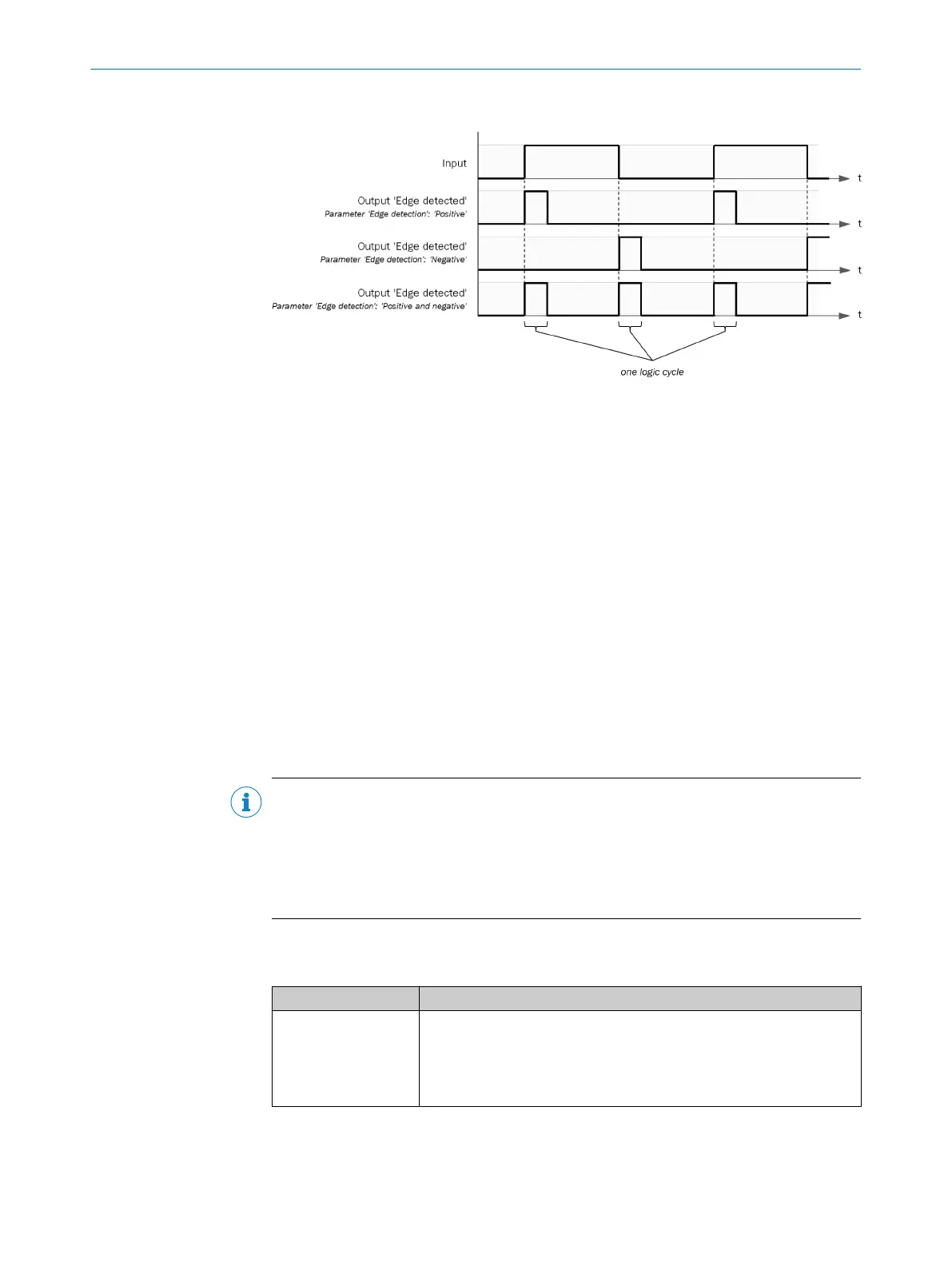
Sequence/timing diagram
Figure 35: Sequence/timing diagram
Complementary information
•
If t
he input is already 1 during the first logic cycle, the function block does not
evaluate this as a positive edge.
•
If the input is already 0 during the first logic cycle, the function block does not
evaluate this as a negative edge.
7.6.2.5 Function blocks for output control
7.6.2.5.1 External device monitoring V1
Overview
T
he function block monitors a switching amplifier with a feedback channel (e.g., a
contactor with positively guided contacts) connected to the Enable output. The function
block checks whether the feedback signal connected to the EDM feedback signal input
switches as expected.
Important information
NOTE
If an ON-
OFF filter or a discrepancy time, for example, is configured for the input signals
in the hardware configuration, then the statuses of the Control input input and the EDM
feedback signal input may differ over time. This can result in an error.
b
Avoid time differences in the signals.
b
Configure the Max. response delay parameter.
Principle of operation
T
able 85: Inputs
Input Description
Control input Data type: Boolean
T
he input must be connected to the logic signal that represents the
desired status for the external device.
If the input in the first logic cycle = 1, then this is evaluated as a rising
edge.
CONFIGURATION 7
8024589/2020-11-10 | SICK O P E R A T I N G I N S T R U C T I O N S | Flexi Compact
79
Subject to change without notice