34 FLOWSIC100 Flare · Addendum to Operating Instructions · 8025365/V1-0/2020-05 · © SICK Engineering GmbH
Installation
4.6.1
Nozzles, blind flanges and seals
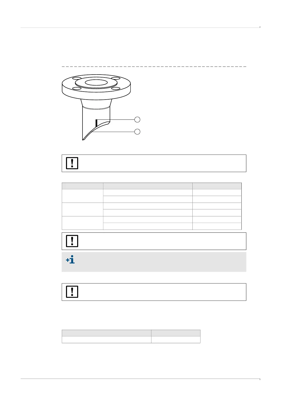
Nozzles are delivered with factory adaption to the nominal pipe diameter, welding bevel and
marking for nozzle alignment according to the gas flow.
Fig. 15 Nozzle
Nozzles and blind flanges
Table 4 Available nozzles and blind flanges
Seals
Flat seals are required for the flange connection between nozzle and ball valve and
between the ball valve and the sender/receiver unit. These seals are included in the
standard scope of delivery of the ball valve and/or sender/receiver unit.
Table 5 Available seals
2
1
1 Welding bevel
2 Marking
NOTICE:
Observe the diagrams on
p. 79, §7.3.
Flange connection Material Temperature ranges
CL150
LTCS P355 QH1 / A350 LF2 -46 … +280°C
SS 1.4401, 1.4404, ASTM A182 Gr. 316, 316L
-196 … +280°C
CL300
LTCS P355 QH1 / A350 LF2 -46 … +280°C
SS 1.4401, 1.4404, ASTM A182 Gr. 316, 316L
-196 … +280°C
PN25 DN50
LTCS P355 QH1 / A350 LF2 -46 … +280°C
SS 1.4401, 1.4404, ASTM A182 Gr. 316, 316L
-196 … +280°C
NOTICE:
Observe the diagrams on
p. 79, §7.3.
To prevent galvanic corrosion between LTCS nozzles and stainless steel ball
valves, a nozzle insulation set (sealing material set with polymer seals and
screwed sleeves) is available as an accessory.
NOTICE:
Observe the diagrams on
p. 79, §7.3.
Material Temperature range
Grooved metal gasket B9A 1.4571 -196 … +280°C

 Loading...


