74 FLOWSIC100 Flare · Addendum to Operating Instructions · 8025365/V1-0/2020-05 · © SICK Engineering GmbH
Technical data
7. 1
FLSE100-XT sender/receiver units
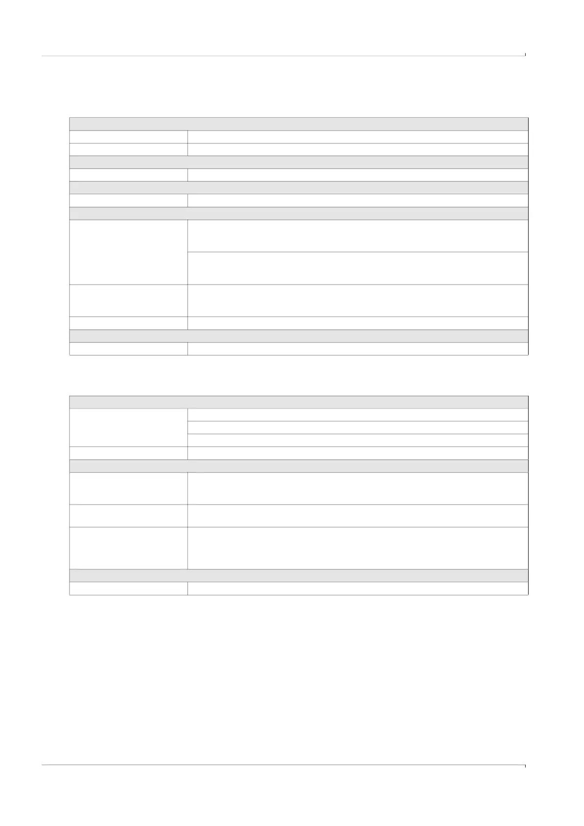
Table 9 Technical data FLSE100-XT
7.1.1
F1F-S
Power supply
Power supply 12…24 V DC, max. 500 mA
Power input < 1 W
Inputs/outputs
Digital data interfaces 1 x RS485, optically isolated
Approvals
Ex approvals ATEX, IECEx, US/C
Ambient conditions
Temperature range Ignition group IIC T4:
-40 °C ... +70 °C
–50 °C ... +70 °C optional
Ignition group IIC T6:
-40 °C ... +55 °C
–50 °C ... +55 °C optional
Storage temperature -40 °C ... +70 °C
–50 °C ... +70 °C optional
Degree of protection IP 66 / 67
Dimensions
Dimensions (W x H x D) Details, see dimension drawings
Table 10 Technical data F1F-S
Measuring conditions
Operating pressure:
1)
CL150 device flange: 20 bar (g)
PN25 device flange (optional): 20 bar (g)
CL300 device flange (optional). 20 bar (g)
Gas temperature –196 °C ... +280 °C
Ex approvals
IECEx Ex db [ia Ga] IIC T6 Ga/Gb
Ex db [ia Ga] IIB T4 Ga/Gb
Ex db [ia Ga] IIA T4 Ga/Gb
ATEX II 1/2G Ex db [ia Ga] IIC T6 Ga/Gb
II 1/2G Ex db [ia Ga] IIC/IIB/IIA T4 Ga/Gb
NEC/CEC (US/CA) Cl I, Div1 Group B, C, D, T4;
Cl I, Zone 1, Ex/AEx d [ia] IIB + H2, T4
Cl I, Div2 Group A, B, C, D, T4;
Cl I, Zone 2, Ex/AEx nA [ia] IIC, T4
Installation
Weight ≤ 12 kg (sensor pair)
1)
Temperature dependent, details see
p. 79, §7.3
»Derating of pressure resistance«

 Loading...


