Installation
FLOWSIC100 Flare · Addendum to Operating Instructions · 8025365/V1-0/2020-05 · © SICK Engineering GmbH 37
4.7
Fitting the nozzles on the pipeline (measuring system without spool
piece)
4.7.1 General preparation work
The installation tool (
p. 36, §4.6.3) contains a foil strip (length approx. 4 times the pipe
diameter, width approx. 0.75 of the pipe diameter) to determine the exact position of the
nozzle on the pipeline. The foil strip is prepared with nozzle markings for different pipe
diameters.
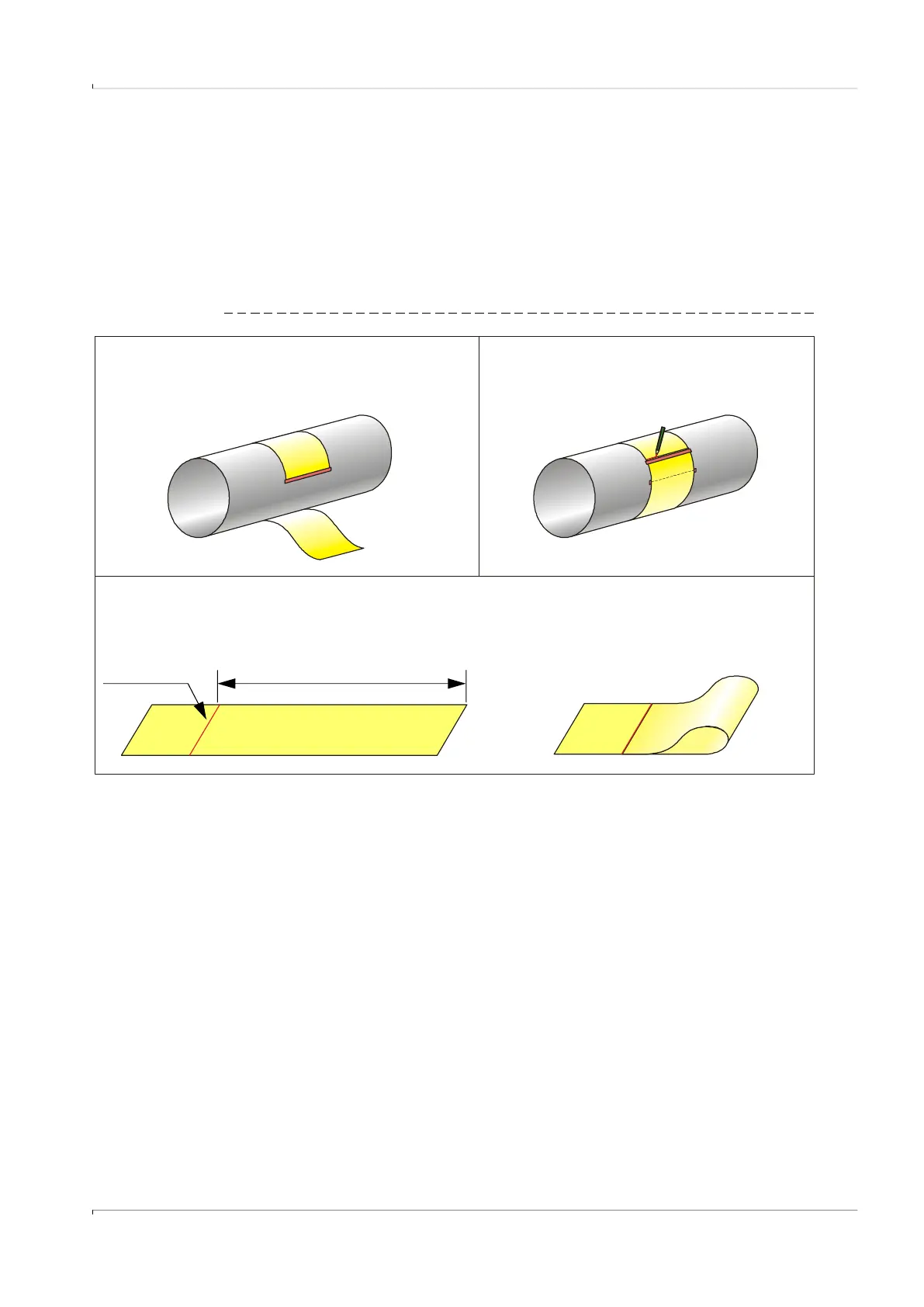
Fig. 17 General preparation work
1) Wind the strip around the pipeline at the selected measur-
ing point (ensure exact right-angled alignment) and secure
(e.g. with adhesive strips).
2) Mark the strip where overlapping starts.
3) Loosen the fastening, take the strip off and lay it out on a level surface.
For 1-path measurements, fold the strip to the overlap
line so that the part matching pipe circumference (U) is
halved.
U
Overlap line

 Loading...


