Installation
FLOWSIC100 Flare · Addendum to Operating Instructions · 8025365/V1-0/2020-05 · © SICK Engineering GmbH 41
4.7.3
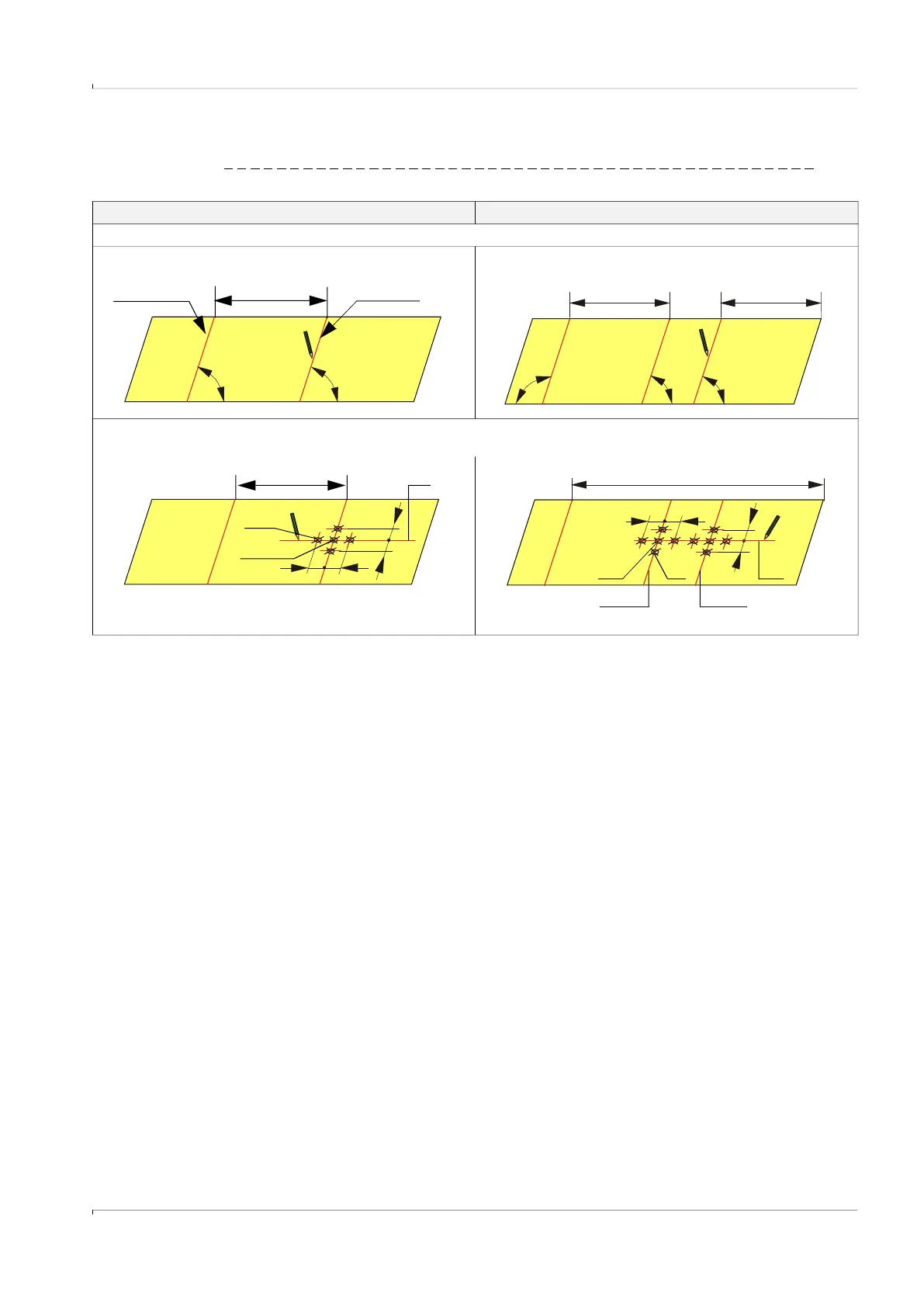
Determining the nozzle position for the probe version
Fig. 21 Determining the nozzle positions on the strip
1-path measurement 2-path measurement
1) Start preparation work as shown in
p. 37, Fig. 17.
5) Draw a guide line (1) for the nozzle position(s), mark crossing points (2) and draw marking points (3) in distance 60 mm (x) from the
crossing points.
Overlap line U/2 Kink line
90 ° 90 °
4a) Roll the strip out again and mark the kink line.
90 ° 90 ° 90 °
4b) Roll the strip out again and mark the lines as follows:
2.498•r 2.498•r
r = U/2
x
x
x x
U/2 1
2
3
x x
U
2 3 1
x
x
Path 1 Path 2

 Loading...


