Electrical installation
FLOWSIC100 Flare · Addendum to Operating Instructions · 8025365/V1-0/2020-05 · © SICK Engineering GmbH 69
5.5
Connection overview
Pin assignment in the terminal compartment of the sender/receiver units
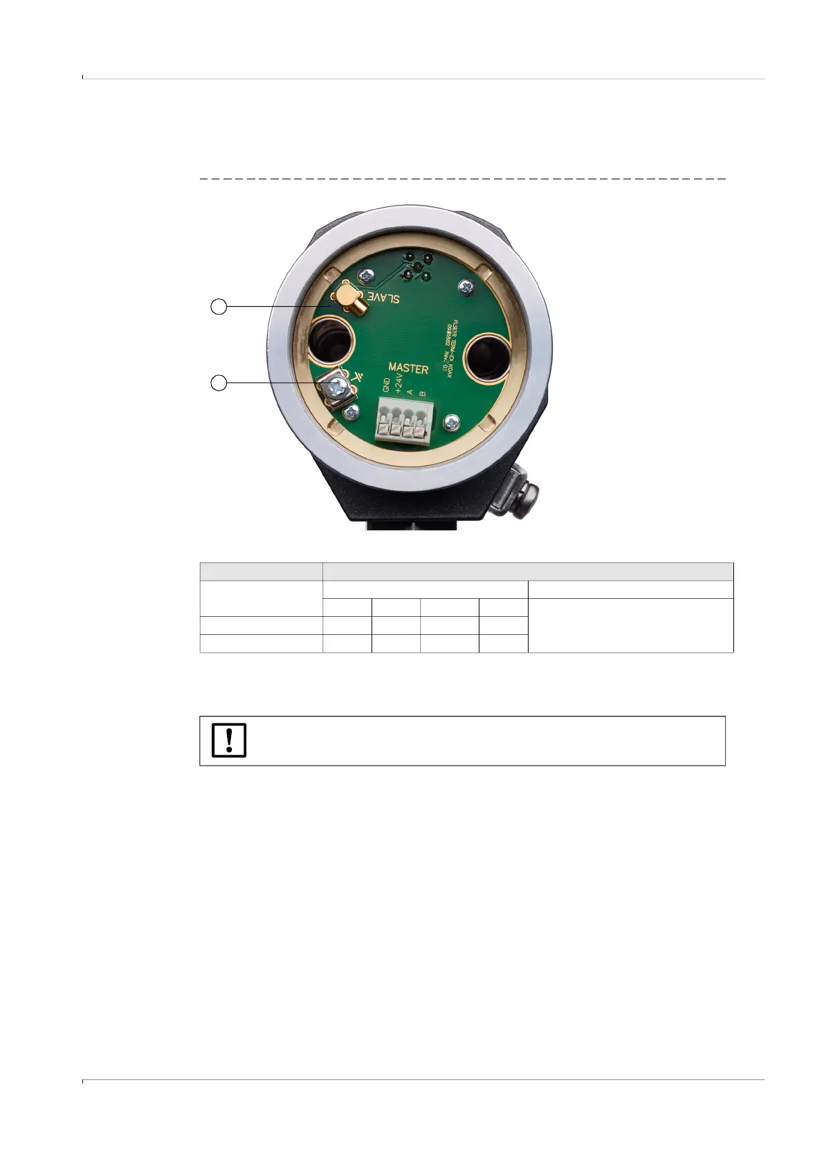
Fig. 40 Terminal compartment FLSE100-XT sender/receiver with electronics (Master)
Table 8 Connection of the sender/receiver units
**: Applicable only for cables with wire color code according to DIN 47100
IF1: Communication between FLSE Master and a higher level control system (Interface 1)
MCX: Signal for FLSE Slave
1
1 Terminal compartment open
2 Grounding terminals
2
Terminals Description
Designation in
terminal compartment
Master Slave
B A +24 V DC GND
MCX connector
External connection ** yellow green white brown
Assignment IF1 IF1 +24 V DC GND
NOTICE:
Self-locking terminals for wire sizes 0.5 .. 1.5 mm² (AWG20 ... AWG16).
 Loading...


