58 FLOWSIC100 Flare · Addendum to Operating Instructions · 8025365/V1-0/2020-05 · © SICK Engineering GmbH
Installation
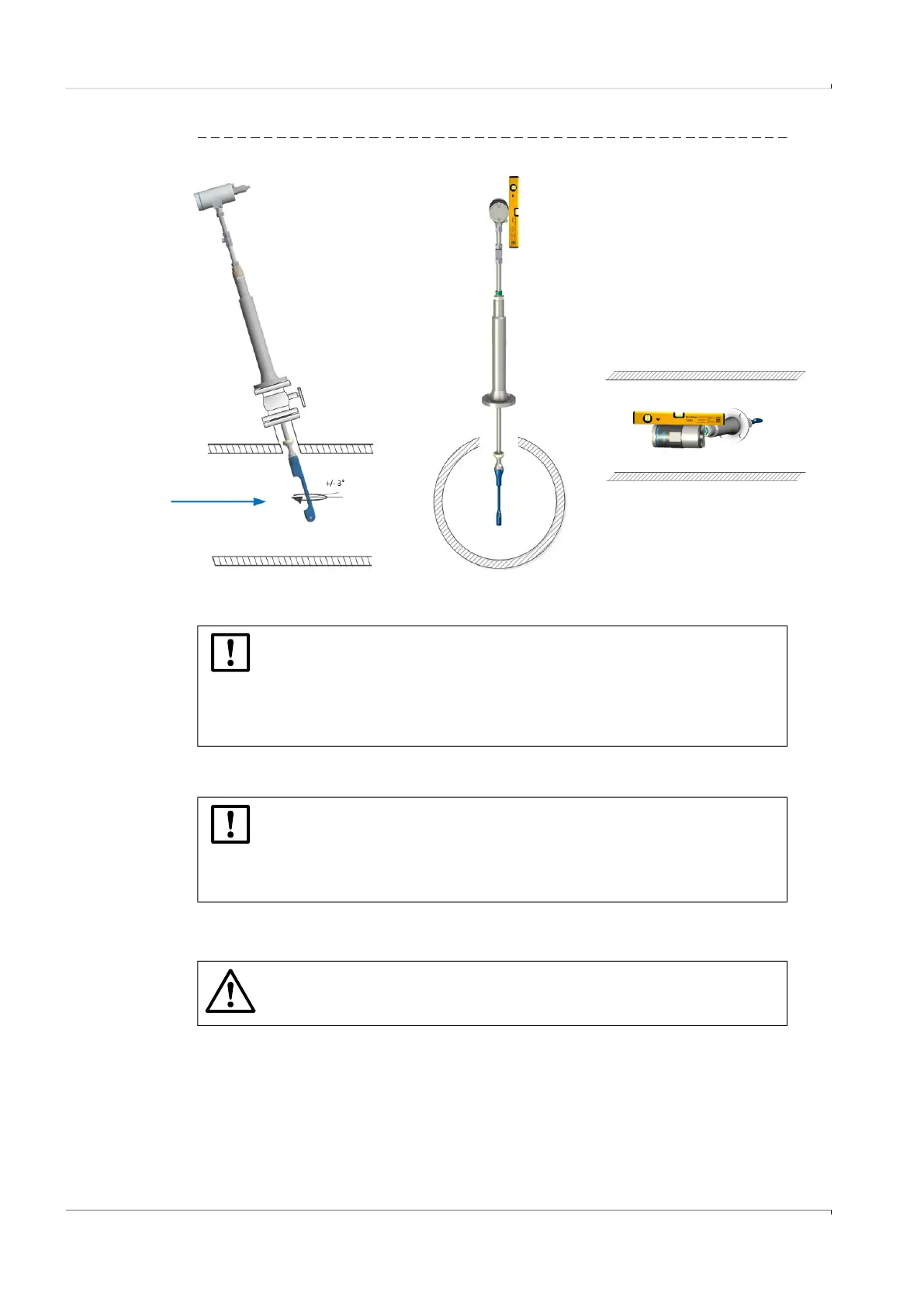
Fig. 35 Alignment of measuring path
4.8.4
Leak tightness check
▸
After a successful leak tightness check, connect the sender/receiver units electrically,
p. 65, §5 .
4. 9 Pulling the sender/receiver units back
1 Completely loosen the cap nut of the self-cutting ring fitting, → Fig. 36.
2 Completely loosen the pipe screw fitting, → Fig. 36.
3 Pull the sender/receiver unit back completely to the stop.
NOTICE:
▸
Perform a leak tightness check with suitable means after completion of the
installation work.
▸
Also perform a leak tightness check with suitable means after completion of
the installation work with spool piece. No leakage check has been made at
the factory.
NOTICE:
Proceed as follows when leak-tightness is not established:
Pull the sender/receiver units back and disconnect them from the process
by closing the ball valve,
p. 58, §4.9.
Contact SICK Service.
WARNING: Hazard through incorrect use of the retraction mechanism
▸
Observe the information on activating the retraction mechanism,
p. 12,
§2.4.

 Loading...


